- 您現(xiàn)在的位置:買賣IC網(wǎng) > PDF目錄385432 > HYB18H512321BF (QIMONDA) 512-Mbit GDDR3 Graphics RAM PDF資料下載
參數(shù)資料
| 型號: | HYB18H512321BF |
| 廠商: | QIMONDA |
| 英文描述: | 512-Mbit GDDR3 Graphics RAM |
| 中文描述: | 512兆GDDR3顯卡內(nèi)存 |
| 文件頁數(shù): | 20/43頁 |
| 文件大?。?/td> | 1344K |
| 代理商: | HYB18H512321BF |
第1頁第2頁第3頁第4頁第5頁第6頁第7頁第8頁第9頁第10頁第11頁第12頁第13頁第14頁第15頁第16頁第17頁第18頁第19頁當前第20頁第21頁第22頁第23頁第24頁第25頁第26頁第27頁第28頁第29頁第30頁第31頁第32頁第33頁第34頁第35頁第36頁第37頁第38頁第39頁第40頁第41頁第42頁第43頁
HYB18H512321BF
512-Mbit GDDR3
Internet Data Sheet
Rev. 1.1, 2007-09
05292007-WAU2-UU95
20
Notes
1. These settings are for debugging purposes only.
2. Default termination values at Power Up.
3. The ODT disable function disables all terminators on the
device.
4. If the user activates bits in the extended mode register in
an optional field, either the optional field is activated (if
option implemented in the device) or no action is taken by
the device (if option not implemented).
5. WR (write recovery time for auto precharge) in clock
cycles is calculated by dividing
t
WR
(in ns) and rounding up
to the next integer (WR[cycles] =
t
WR
[ns] /
t
CK
[ns]). The
mode register must be programmed to this value.
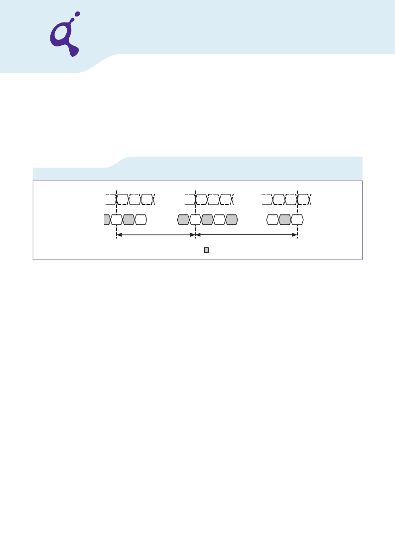
FIGURE 9
Extended Mode Register Set Timing
4.2.1
DLL enable
The DLL must be enabled for normal operation. DLL enable is required during power-up initialization and upon returning to
normal operation after having disabled the DLL. (When the device exits self-refresh mode, the DLL is enabled automatically).
Anytime the DLL is enabled, 1000 cycles must occur before a READ command can be issued.
4.2.2
WR
The WR parameter is programmed using the register bits A4, A5 and A7. This integer parameter defines as a number of clock
cycles the Write Recovery time in a Write with Autoprecharge operation.
The following inequality has to be complied with: WR *
t
CK
≥
t
WR
, where
t
CK
is the clock cycle time. The high-speed bitmap
supports WR from 7 to 13. The mid-range bitmap provides WR cycles from 4 to 11.
4.2.3
Termination Rtt
The data termination, Rtt, is used to set the value of the internal termination resistors. The GDDR3 DRAM supports ZQ / 4 and
ZQ / 2 termination values. The termination may also be disabled for testing and other purposes.
4.2.4
Output Driver Impedance
The Output Driver Impedance extended mode register is used to set the value of the data output driver impedance. When the
auto calibration is used, the output driver impedance is set nominally to ZQ / 6.
If the Output Driver Impendance is changed to 30, 40 or 45 Ohms the user needs to issue 16 AREF commands separated by
t
RFC
consecutively to make the change effective. The user must be aware that the Command bus needs to be stable for a time
of
t
KO
after each AREF.
CLK#
CLK
Don't Care
PA
EMRS
NOP
A.C.
NOP
t
RP
t
MRD
Command
EMRS: Extended MRS command
PA: PREALL command
A.C.: Any command
NOP
相關PDF資料 |
PDF描述 |
|---|---|
| HYB18L128160BF | DRAMs for Mobile Applications 128-Mbit Mobile-RAM |
| HYB18L256160B | DRAMs for Mobile Applications 256-Mbit Mobile-RAM |
| HYMP112S64LMP8-C4 | DDR2 SDRAM SO-DIMM |
| HYMP112S64LMP8-C5 | DDR2 SDRAM SO-DIMM |
| HYMP112S64LMP8-E3 | BNC FEMALE TO RCA MALE COUPLER |
相關代理商/技術參數(shù) |
參數(shù)描述 |
|---|---|
| HYB18H512321BF-08/10 | 制造商:QIMONDA 制造商全稱:QIMONDA 功能描述:512-Mbit GDDR3 Graphics RAM |
| HYB18H512321BF-11/12/14 | 制造商:QIMONDA 制造商全稱:QIMONDA 功能描述:512-Mbit GDDR3 Graphics RAM |
| HYB18L128160BC-7.5 | 制造商:QIMONDA 制造商全稱:QIMONDA 功能描述:DRAMs for Mobile Applications 128-Mbit Mobile-RAM |
| HYB18L128160BC-75 | 制造商:INFINEON 制造商全稱:Infineon Technologies AG 功能描述:DRAMs for Mobile Applications |
| HYB18L128160BF | 制造商:QIMONDA 制造商全稱:QIMONDA 功能描述:DRAMs for Mobile Applications 128-Mbit Mobile-RAM |
發(fā)布緊急采購,3分鐘左右您將得到回復。