- 您現(xiàn)在的位置:買賣IC網(wǎng) > PDF目錄371892 > HSDL-3600 RES THICK FILM POWER 30 OHM 25W PDF資料下載
參數(shù)資料
| 型號(hào): | HSDL-3600 |
| 英文描述: | RES THICK FILM POWER 30 OHM 25W |
| 中文描述: | 紅外符合4 Mb / s的3伏紅外線收發(fā)器 |
| 文件頁(yè)數(shù): | 16/34頁(yè) |
| 文件大小: | 567K |
| 代理商: | HSDL-3600 |
第1頁(yè)第2頁(yè)第3頁(yè)第4頁(yè)第5頁(yè)第6頁(yè)第7頁(yè)第8頁(yè)第9頁(yè)第10頁(yè)第11頁(yè)第12頁(yè)第13頁(yè)第14頁(yè)第15頁(yè)當(dāng)前第16頁(yè)第17頁(yè)第18頁(yè)第19頁(yè)第20頁(yè)第21頁(yè)第22頁(yè)第23頁(yè)第24頁(yè)第25頁(yè)第26頁(yè)第27頁(yè)第28頁(yè)第29頁(yè)第30頁(yè)第31頁(yè)第32頁(yè)第33頁(yè)第34頁(yè)
16
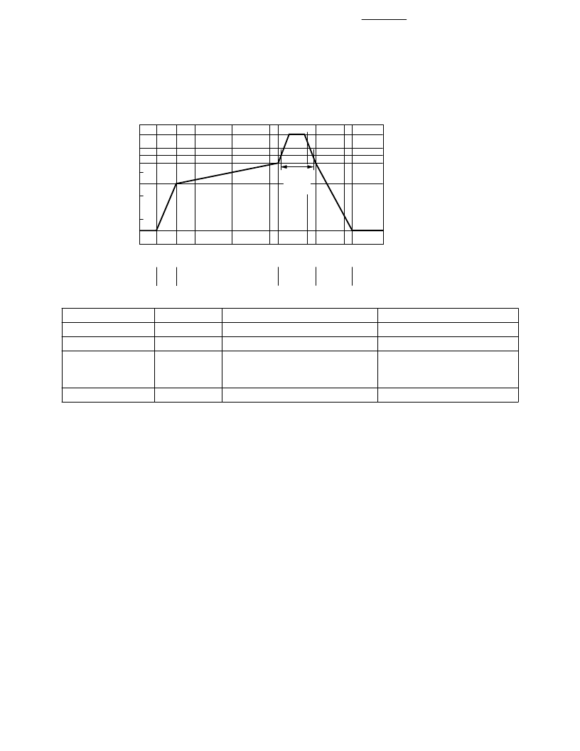
Reflow Profile
Process Zone
Heat Up
Solder Paste Dry
Symbol
P1, R1
P2, R2
P3, R3
T
Maximum
T/
time
4
°
C/s
0.5
°
C/s
4
°
C/s
25
°
C to 125
°
C
125
°
C to 170
°
C
170
°
C to 230
°
C
(245
°
C at 10 seconds max.)
230
°
C to 170
°
C
170
°
C to 25
°
C
Solder Reflow
P3, R4
P4, R5
-4
°
C/s
-3
°
C/s
Cool Down
The reflow profile is a straight-
line representation of a nominal
temperature profile for a
convective reflow solder process.
The temperature profile is divided
into four process zones, each
with different
T/
time
temperature change rates. The
T/
time rates are detailed in the
above table. The temperatures
are measured at the component
to printed circuit board
connections.
In
process zone P1
, the PC
board and HSDL-3600
castellation I/O pins are heated to
a temperature of 125
°
C to
activate the flux in the solder
paste. The temperature ramp up
rate, R1, is limited to 4
°
C per
second to allow for even heating
of both the PC board and HSDL-
3600 castellation I/O pins.
Process zone P2
should be of
sufficient time duration (> 60
seconds) to dry the solder paste.
The temperature is raised to a
level just below the liquidus point
of the solder, usually 170
°
C
(338
°
F).
Process zone P3
is the solder
reflow zone. In zone P3, the
temperature is quickly raised
above the liquidus point of solder
to 230
°
C (446
°
F) for optimum
results. The dwell time above the
liquidus point of solder should be
between 15 and 90 seconds. It
usually takes about 15 seconds to
assure proper coalescing of the
solder balls into liquid solder and
the formation of good solder
connections. Beyond a dwell time
of 90 seconds, the intermetallic
growth within the solder
connections becomes excessive,
resulting in the formation of weak
and unreliable connections. The
temperature is then rapidly
reduced to a point below the
solidus temperature of the solder,
usually 170
°
C (338
°
F), to allow
the solder within the connections
to freeze solid.
Process zone P4
is the cool
down after solder freeze. The
cool down rate, R5, from the
liquidus point of the solder to
25
°
C (77
°
F) should not exceed
-3
°
C per second maximum. This
limitation is necessary to allow
the PC board and HSDL-3600
castellation I/O pins to change
dimensions evenly, putting
minimal stresses on the
HSDL-3600 transceiver.
0
t-TIME (SECONDS)
P2
SOLDER PASTE DRY
T
200
183
170
150
125
100
50
50
150
100
200
250
300
230
P1
HEAT
UP
P3
SOLDER
REFLOW
P4
COOL
DOWN
25
R1
R2
R3
R4
R5
90 sec.
MAX.
ABOVE
183°C
MAX. 245°C
相關(guān)PDF資料 |
PDF描述 |
|---|---|
| HSDL-3612 | IrDA Data Compliant 115.2kb/s 3V to 5V Infrared Transceiver |
| HSDL-3612-007 | IrDA Data Compliant 115.2kb/s 3V to 5V Infrared Transceiver |
| HSDL-3612-008 | IrDA Data Compliant 115.2kb/s 3V to 5V Infrared Transceiver |
| HSDL-3612-037 | IrDA Data Compliant 115.2kb/s 3V to 5V Infrared Transceiver |
| HSDL-3612-038 | IrDA Data Compliant 115.2kb/s 3V to 5V Infrared Transceiver |
相關(guān)代理商/技術(shù)參數(shù) |
參數(shù)描述 |
|---|---|
| HSDL-3600#007 | 制造商:Hewlett Packard Co 功能描述:SPECIALTY INTERFACE CIRCUIT, SMA10 |
| HSDL-3600#008 | 制造商:Hewlett Packard Co 功能描述:SPECIALTY INTERFACE CIRCUIT, SMA10 |
| HSDL-3600#017 | 制造商:未知廠家 制造商全稱:未知廠家 功能描述:FIBER OPTIC TRANSCEIVER |
| HSDL-3600#018 | 制造商:未知廠家 制造商全稱:未知廠家 功能描述:FIBER OPTIC TRANSCEIVER |
| HSDL3600008 | 制造商:AGILENT 功能描述:NEW |
發(fā)布緊急采購(gòu),3分鐘左右您將得到回復(fù)。