- 您現(xiàn)在的位置:買賣IC網(wǎng) > PDF目錄383073 > HMC106 SPDT RF Reflective Switch PDF資料下載
參數(shù)資料
| 型號(hào): | HMC106 |
| 英文描述: | SPDT RF Reflective Switch |
| 中文描述: | 擲射頻反射開關(guān) |
| 文件頁數(shù): | 12/15頁 |
| 文件大?。?/td> | 190K |
| 代理商: | HMC106 |

HMC10XX FAMILY
Simple Circuit Application
12
The circuit in Figure 15 shows a simple magnetic sensor.
This circuit acts as a proximity sensor and will turn on the
LED when a magnet is brought within 0.25 to 0.5 inch of the
sensor. The amplifier acts as a simple comparator and
switches low when the HMC1001 bridge output exceeds
* R1 or R2 used to trim offest
# provides 1KHz rolloff
Vref
Magnetic
Sensor
1.5nF#
650
R1*
R2*
-
+
25K
LM440
2.5V
V+
AMP04
H
Vout
1
8
6
5
2
3
Ain+
Ain-
Ref+
Ref-
Gnd
CONV
SCLK
SDATA
NDRDY
XIN
CAL
NCS
1.6
V+
7
4
8
5
1
3
7
8
9
10
2
14
15
16
4
3
1
CS5509
16 bit A/D
12
V+
6,11,13
+5V
S
I
+5V
S/R
Pulse
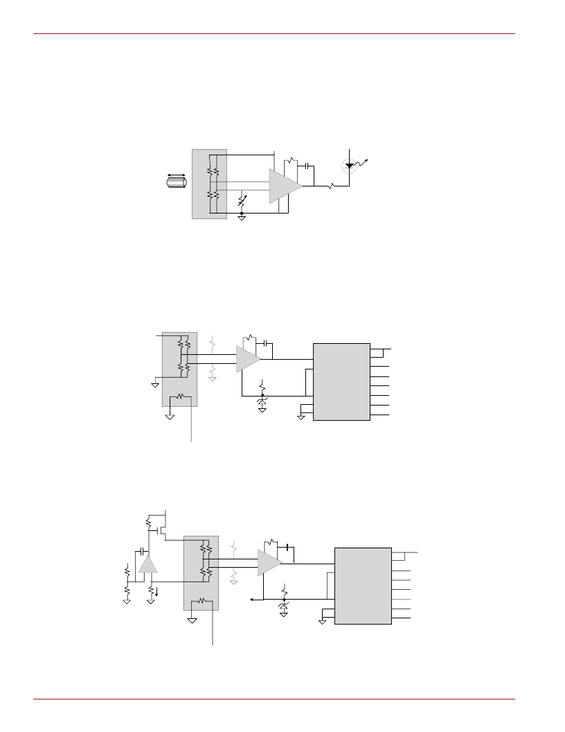
Figure 16—One-Axis Sensor With Digital Interface
* R1 or R2 used to trim offest
**R3 = 451
for 1 axis, 921
for 2 axis, or 1411
for 3 axis
# provides 1KHz rolloff
Vref
Magnetic
Sensor
1.5nF#
650
R1*
R2*
-
+
25K
LM440
2.5V
V+
AMP04
H
Vout
1
8
6
5
2
3
Ain+
Ain-
Ref+
Ref-
Gnd
CONV
SCLK
SDATA
NDRDY
XIN
CAL
NCS
1.6
V+
7
4
8
5
1
3
7
8
9
10
2
14
15
16
4
3
1
CS5509
16 bit A/D
12
V+
6,11,13
+5V
S
I
+6-15V
S/R
Pulse
10
-
+
Vref
22.1K
R3**
B
100K
LMC7101
5 mA
0.01
1
3
4
Figure 17—One-Axis Sensor With Constant Bridge Current and Digital Interface
30mV. The magnet must be strong (200 gauss) and have
one of its magnetic poles point along the sensitive direction
of the sensor. This circuit can be used to detect a door open/
closed status or the presence or absence of an item. Figures
16, 17 and 18 show other circuit examples.
4
Gain=1000, BW=10Hz
* R1 is used to trim switchpoint
# provides 10Hz rolloff
Magnetic
Sensor
0.15μF#
100
R1*
+
-
AMP04
H
1
8
6
5
3
2
7
4
8
5
+5V
7
400
+5V
Calibrate:
1. Trim R1 for (+V) - (-V) < 30mV
2. Apply signal < 30mV, LED should be off.
3. Apply signal > 30mV, LED should be on.
V-
V+
Vout
LED
magnet
Figure 15—Magnetic Proximity Switch
相關(guān)PDF資料 |
PDF描述 |
|---|---|
| HMC109 | Analog Attenuator |
| HMC160QS16 | Interface IC |
| HMC160S14 | Interface IC |
| HMC162C8 | Analog IC |
| HMC167SS8 | Interface IC |
相關(guān)代理商/技術(shù)參數(shù) |
參數(shù)描述 |
|---|---|
| HMC1060LP3E | 制造商:Hittite Microwave Corp 功能描述:IC REG LDO ADJ 16SMT |
| HMC1060LP3ETR | 制造商:Hittite Microwave Corp 功能描述:HMC1060 Series Quad Output 500 mA Linear Voltage Regulator - 3x3 mm QFN-16 |
| HMC1061LC5 | 制造商:Hittite Microwave Corp 功能描述:IC AMP TRACK&HOLD 4GS/S 32SMD |
| HMC1063LP3E | 制造商:Hittite Microwave Corp 功能描述:IC MMIC IQ MIXER GAAS 16SMD |
| HMC1065LP4E | 制造商:Hittite Microwave Corp 功能描述:IC MMIC IQ DOWNCONV 24SMD |
發(fā)布緊急采購,3分鐘左右您將得到回復(fù)。