- 您現(xiàn)在的位置:買賣IC網(wǎng) > PDF目錄371804 > HF88S05(S) PDF資料下載
參數(shù)資料
| 型號: | HF88S05(S) |
| 文件頁數(shù): | 8/13頁 |
| 文件大小: | 277K |
| 代理商: | HF88S05(S) |

Command Mode SRAM HF88S05
-8-
02/07/01
8.
Serial Mode
The serial interface is preferable to parallel interface in applications where I/O pins are
limited. The interface logic circuit is basically the same as the parallel mode except that an
internal shift register and bit counter are used to facilitate transferring serial data from/to
external MCU.
Multiple devices array can also be used in serial mode. The chip array is connected in daisy
chain manner. The MCU’s serial data output pin drives the SDI pin of the first device.
The SDO pin of the device then, in turn, drives the SDI pin of the next device in the chain.
The SDO pin of the last device then connects back to the MCU’s SDI pin to complete the
loop.
There could be only one active device in the array at one time, while the other device must be
deselected.
8.1.
Bi-directional Synchronous Serial Data Interface
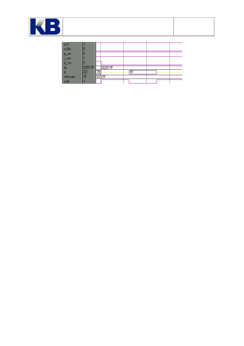
The Serial interface is a Bi-directional Synchronous Serial Interface. The Serial Data can be
written to Registers (such as TPL, TPH, TPP registers) as well as SRAM through the serial
interface. The Checksum and SRAM contents can also be read through Serial Interface, too.
The Serial Data Input SDI pin is connected to LSB of internal shift register. With each
rising edge of SCLK pin, the SDI input is shifted into the shift register. At the eighth rising
edge of SCLK, the content of shift Register is transferred from/to registers or SRAM
depending on the status of D_Cn and R_Wn.
If R_Wn is at “high” state at the eighth rising edge of SCLK then either the contents of
相關(guān)PDF資料 |
PDF描述 |
|---|---|
| HFA-0003L | Ultra High Speed Comparator |
| HFA3-0003-5 | Ultra High Speed Comparator |
| HFA3-0003-9 | Ultra High Speed Comparator |
| HFA3-0003L-5 | Ultra High Speed Comparator |
| HFA3-0003L-9 | Ultra High Speed Comparator |
相關(guān)代理商/技術(shù)參數(shù) |
參數(shù)描述 |
|---|---|
| HF88Z-2Z DIE | 制造商:Maxim Integrated Products 功能描述: |
| HF89DEF | 制造商:未知廠家 制造商全稱:未知廠家 功能描述:SUBMINIATURE POWER RELAY |
| HF89DENIL | 制造商:未知廠家 制造商全稱:未知廠家 功能描述:SUBMINIATURE POWER RELAY |
| HF89DNILF | 制造商:未知廠家 制造商全稱:未知廠家 功能描述:SUBMINIATURE POWER RELAY |
| HF89DNILNIL | 制造商:未知廠家 制造商全稱:未知廠家 功能描述:SUBMINIATURE POWER RELAY |
發(fā)布緊急采購,3分鐘左右您將得到回復(fù)。