- 您現(xiàn)在的位置:買賣IC網(wǎng) > PDF目錄384398 > HE84760B (King Billion Electronics Co., Ltd.) 8-bit Micro-controller PDF資料下載
參數(shù)資料
| 型號: | HE84760B |
| 廠商: | King Billion Electronics Co., Ltd. |
| 英文描述: | 8-bit Micro-controller |
| 中文描述: | 8位微控制器 |
| 文件頁數(shù): | 39/51頁 |
| 文件大?。?/td> | 487K |
| 代理商: | HE84760B |
第1頁第2頁第3頁第4頁第5頁第6頁第7頁第8頁第9頁第10頁第11頁第12頁第13頁第14頁第15頁第16頁第17頁第18頁第19頁第20頁第21頁第22頁第23頁第24頁第25頁第26頁第27頁第28頁第29頁第30頁第31頁第32頁第33頁第34頁第35頁第36頁第37頁第38頁當前第39頁第40頁第41頁第42頁第43頁第44頁第45頁第46頁第47頁第48頁第49頁第50頁第51頁
21.2.
Baud Rate Configuration Register
KING BILLION ELECTRONICS CO., LTD
駿
億
電
子
股
份
有
限
公
司
HE84760B
HE80004 Series
June 29, 2005
This specification is subject to change without notice. Please contact sales person for the latest version before use.
39
V1.0
The BRH and BRL registers hold the upper and lower bytes of 16 bit baud rate divisor and which are
readable/writable. The baud rate of UART is calculated as following:
RATE
BAUD
FCK
DIVISOR
RATE
BAUD
_
*
16
_
_
=
, (
FCK: fast clock of system
)
The contents of BRH and BRL are calculated by the following two formulas:
BRL =
DIVISOR
RATE
BAUD
_
_
% 256
BRH = (
DIVISOR
RATE
BAUD
_
_
– BRL) / 256
The “%” symbol is the modulus operation (reminder of division). For example, if the FCK is 1.8432M Hz
and the desired baud rate is 2400 baud, then
48
2400
*
16
1843200
_
_
=
=
DIVISOR
RATE
BAUD
The BRL register shall be set to 0x30 and BRH set to 0x00. The setting of baud_rate_divisor is not
updated until the BRH register is written. Thus user is strongly recommended to write BRL first, then
BRH.
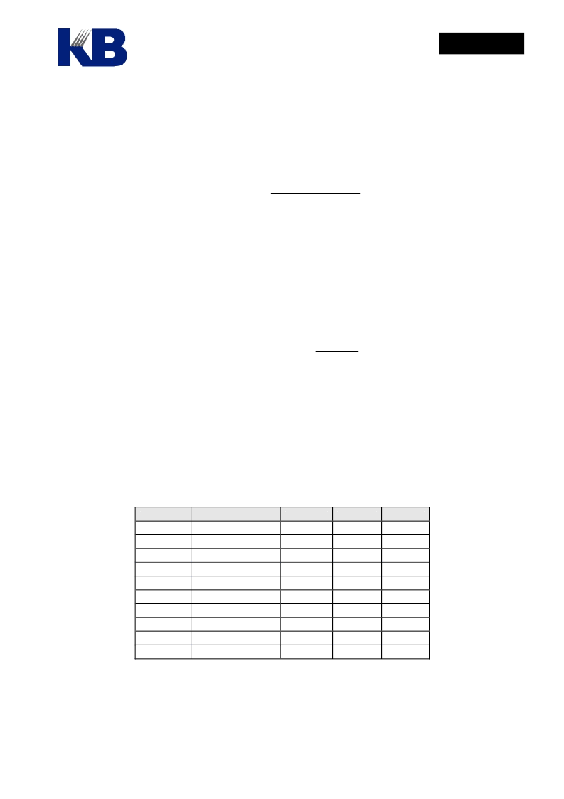
In order to obtain good communication quality, the same time base shall be used in the both sides of
transmitting and receiving. The following table shows the most common baud rate setting used in the PC
UART communication.
BRL and BRH: Baud Rate Control Registers
FCK(Hz) Baud Rate (bps)
1.8432M
50
1.8432M
300
1.8432M
1200
1.8432M
2400
1.8432M
4800
1.8432M
9600
1.8432M
19200
1.8432M
38400
1.8432M
57600
1.8432M
115200
Divisor
2304
384
96
48
24
12
6
3
2
1
BRL
0x00
0x80
0x60
0x30
0x18
0x0C
0x06
0x03
0x02
0x01
BRH
0x09
0x01
0x00
0x00
0x00
0x00
0x00
0x00
0x00
0x00
相關PDF資料 |
PDF描述 |
|---|---|
| HE84760 | 8-bit Micro-controller |
| HE84761 | 8-bit Micro-controller |
| HE847701 | 8-bit Micro-controller |
| HE84770D | 8-bit Micro-controller |
| HE84770 | 8-bit Micro-controller |
相關代理商/技術參數(shù) |
參數(shù)描述 |
|---|---|
| HE84761 | 制造商:KB 制造商全稱:KB 功能描述:8-bit Micro-controller |
| HE84761(S) | 制造商:未知廠家 制造商全稱:未知廠家 功能描述: |
| HE84762(S) | 制造商:未知廠家 制造商全稱:未知廠家 功能描述: |
| HE84770 | 制造商:KB 制造商全稱:KB 功能描述:8-bit Micro-controller |
| HE84770(S) | 制造商:未知廠家 制造商全稱:未知廠家 功能描述: |
發(fā)布緊急采購,3分鐘左右您將得到回復。