- 您現在的位置:買賣IC網 > PDF目錄370462 > HD404459 (Hitachi,Ltd.) 4-bit HMCS400-Series microcomputer(4位單片微計算機) PDF資料下載
參數資料
| 型號: | HD404459 |
| 廠商: | Hitachi,Ltd. |
| 英文描述: | 4-bit HMCS400-Series microcomputer(4位單片微計算機) |
| 中文描述: | 4位HMCS400系列微機(4位單片微計算機) |
| 文件頁數: | 30/120頁 |
| 文件大?。?/td> | 692K |
| 代理商: | HD404459 |
第1頁第2頁第3頁第4頁第5頁第6頁第7頁第8頁第9頁第10頁第11頁第12頁第13頁第14頁第15頁第16頁第17頁第18頁第19頁第20頁第21頁第22頁第23頁第24頁第25頁第26頁第27頁第28頁第29頁當前第30頁第31頁第32頁第33頁第34頁第35頁第36頁第37頁第38頁第39頁第40頁第41頁第42頁第43頁第44頁第45頁第46頁第47頁第48頁第49頁第50頁第51頁第52頁第53頁第54頁第55頁第56頁第57頁第58頁第59頁第60頁第61頁第62頁第63頁第64頁第65頁第66頁第67頁第68頁第69頁第70頁第71頁第72頁第73頁第74頁第75頁第76頁第77頁第78頁第79頁第80頁第81頁第82頁第83頁第84頁第85頁第86頁第87頁第88頁第89頁第90頁第91頁第92頁第93頁第94頁第95頁第96頁第97頁第98頁第99頁第100頁第101頁第102頁第103頁第104頁第105頁第106頁第107頁第108頁第109頁第110頁第111頁第112頁第113頁第114頁第115頁第116頁第117頁第118頁第119頁第120頁
HD404459 Series
30
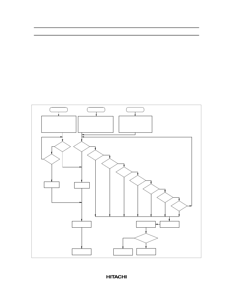
Standby Mode:
In standby mode, the oscillators continue to operate, but the clocks related to instruction
execution stop. Therefore, the CPU operation stops, but all RAM and register contents are retained, and the
D or R port status, when set to output, is maintained. Peripheral functions such as interrupts, timers, and
serial interface continue to operate. The power dissipation in this mode is lower than in active mode since
the CPU halts.
The MCU enters standby mode when the SBY instruction is executed in active mode.
Standby mode is terminated by RESET input or an interrupt request. If it is terminated by RESET, the
MCU is reset as well. After an interrupt request, the MCU enters active mode and executes the next
instruction after the SBY instruction. If the interrupt enable flag is 1, the interrupt is then processed; if it is
0, the interrupt request is left pending and normal instruction execution continues. See figure 15 for the
flowchart of operation in standby mode.
Standby
Oscillator: Active
Peripheral clocks: Active
All other clocks: Stop
No
Yes
No
Yes
No
Yes
No
Yes
No
Yes
No
Yes
Yes
(SBY
only)
Watch
Oscillator: Stop
Suboscillator: Active
Peripheral clocks: Stop
All other clocks: Stop
Restart
processor clocks
Reset MCU
Execute
next instruction
Accept interrupt
Restart
processor clocks
No
Yes
RESET = 1
IF0
IM0
= 1
IF1
IM1
= 1
IFTD
IMTD
= 1
IF + IF2
IMTA
IM2
= 1
IF + IF3
IMTB
IM3
= 1
No
Yes
No
Stop
Oscillator: Stop
Suboscillator: Active/Stop
Peripheral clocks: Stop
All other clocks: Stop
RESET = 1
STOPC
= 0
RAME = 1
RAME = 0
Yes
Yes
No
No
(SBY
only)
(SBY
only)
(SBY
only)
Execute
next instruction
IF = 1,
IM = 0, and
IE = 1
*
Note:
*
The INT
interrupt
is valid only by
standby mode
cancellation.
IFWU
IMWU
= 1
IF + IFS
IMTC
IMS
= 1
Figure 15 MCU Operation Flowchart
相關PDF資料 |
PDF描述 |
|---|---|
| HD40A4052 | 4-Bit Single-Chip Microcomputer(4位單片微計算機) |
| HD404092 | 4-Bit Single-Chip Microcomputer(4位單片微計算機) |
| HD404094 | 4-Bit Single-Chip Microcomputer(4位單片微計算機) |
| HD4074094 | 4-Bit Single-Chip Microcomputer(4位單片微計算機) |
| HD404052 | 4-Bit Single-Chip Microcomputer(4位單片微計算機) |
相關代理商/技術參數 |
參數描述 |
|---|---|
| HD404459H | 制造商:RENESAS 制造商全稱:Renesas Technology Corp 功能描述:4-bit HMCS400-series microcomputers |
| HD404459SERIES | 制造商:未知廠家 制造商全稱:未知廠家 功能描述: |
| HD404508FS | 制造商:未知廠家 制造商全稱:未知廠家 功能描述:4-Bit Microcontroller |
| HD404608FS | 制造商:未知廠家 制造商全稱:未知廠家 功能描述:4-Bit Microcontroller |
| HD404608H | 制造商:未知廠家 制造商全稱:未知廠家 功能描述:4-Bit Microcontroller |
發(fā)布緊急采購,3分鐘左右您將得到回復。