- 您現(xiàn)在的位置:買賣IC網(wǎng) > PDF目錄385344 > GS9023-CFY (Electronic Theatre Controls, Inc.) Aluminum Electrolytic Radial Leaded Bi-Polar Capacitor; Capacitance: 100uF; Voltage: 63V; Case Size: 12.5x20 mm; Packaging: Bulk PDF資料下載
參數(shù)資料
| 型號: | GS9023-CFY |
| 廠商: | Electronic Theatre Controls, Inc. |
| 英文描述: | Aluminum Electrolytic Radial Leaded Bi-Polar Capacitor; Capacitance: 100uF; Voltage: 63V; Case Size: 12.5x20 mm; Packaging: Bulk |
| 中文描述: | 嵌入式音頻編解碼器 |
| 文件頁數(shù): | 13/33頁 |
| 文件大?。?/td> | 301K |
| 代理商: | GS9023-CFY |
第1頁第2頁第3頁第4頁第5頁第6頁第7頁第8頁第9頁第10頁第11頁第12頁當前第13頁第14頁第15頁第16頁第17頁第18頁第19頁第20頁第21頁第22頁第23頁第24頁第25頁第26頁第27頁第28頁第29頁第30頁第31頁第32頁第33頁

GENNUM CORPORATION
522 - 45 - 05
13
G
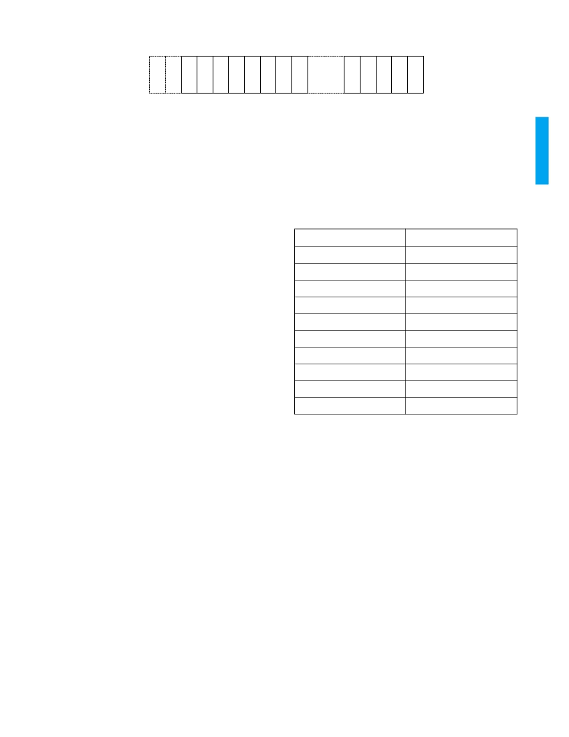
Fig. 7: Extended Audio Data Packet Structure
To select 24 bit audio operation, the user must set the
AUXEN pin or the
“
A4ON
”
bit of Host Interface Register #1h
HIGH. When the AUXEN pin or
“
A4ON
”
bit is HIGH, the
GS9023 does not multiplex the audio data packet and the
associated extended audio data packet if there is
insufficient room for both in the HANC space. In this case,
the
“
ADERR
”
bit of Host Interface Register #7h is set HIGH,
indicating an audio packet multiplexing error. The error bit is
cleared when accessed by the Host Interface. The audio
group (Extended packet data ID) for each device is
configured in
“
AD4ID[3:0]
”
of Host Interface Register #3h.
On power up, audio group 1 is selected by default.
By cascading four GS9023 devices, it is possible to
multiplex up to 16 audio channels (according to SMPTE
272) in a component video signal as shown in Figure 18.
NOTE: In the 525/D1 video format, only 15 channels of 24
bit audio can be multiplexed in the cascade configuration.
The extended audio data packet structure as described in
SMPTE 272M is shown in Figure 7.
The extended audio data packets words are defined as
follows:
ADF: Ancillary Data Flag.
The ancillary data flag marks the
beginning of an ancillary packet and is automatically
generated by the GS9023.
DID: Data ID.
Extended audio data packets corresponding
to an audio group are selected by programming
“
A4ID[3:0]
”
of Host Interface Register #3h for audio groups 1 to 4 as
follows:
Group 1: Eh (1FEh)
Group 2: Ch (2FCh)
Group 3: Ah (2FAh)
Group 4: 8h (1F8h)
NOTE: The six most significant bits of the DID are
automatically generated by the GS9023.
DBN: Data Block Number.
The data block number is used
when data blocks within a common data ID are to be linked
or to distinguish consecutive data blocks within a common
data ID. The data block number continuously increments
from 1 to 255 and is generated automatically by the
GS9023.
DC: Data Count.
The data count represents the number of
user data words to follow (maximum of 255 words). The
data count is automatically generated by the GS9023.
DATA WORDS:
The extended audio data samples are
mapped into ancillary data words as shown in Table 5.
The extended audio packet data sample bits are defined as
follows:
x[3:0]:
Auxiliary data from subframe 1.
y[3:0]:
Auxiliary data from subframe 2.
a: Address pointer.
LOW for channels 1 and 2, and HIGH for
channels 3 and 4. This bit is internally generated by the
GS9023.
CS: Checksum.
The checksum consists of nine bits. The
checksum is used to determine the validity of the words
data ID through user data. It is the sum of the nine least
significant bits of the words data ID through user data. The
checksum is automatically generated by the GS9023.
Audio Control Packets
The audio control packet structure is detailed in SMPTE
272M. The audio group (Audio control packet data ID) for
each device is configured in
“
ACID[3:0]
”
of Host Interface
Register #4h. The Audio control parameters are configured
in Host Interface Registers #Ah, #Bh, #Ch and #Dh. The
audio control packet multiplexing positions for the various
A
A
A
D
D
D
A
C
* The ancillary data flag, ADF, is one word in composite systems (ANSI/SMPTE 259M)
and three words in component systems (ANSI/SMPTE 125M).
A
A
A
A
A
A
A
TABLE 5: Extended Audio Packet Data Sample Structure
BIT
ANC DATA WORD
b9
not b8
b8
a
b7
y3 (MSB)
b6
y2
b5
y1
b4
y0 (LSB)
b3
x3 (MSB)
b2
x2
b1
x1
b0
x0 (LSB)
相關PDF資料 |
PDF描述 |
|---|---|
| GS9024 | Automatic Cable Equalizer |
| GS9024-CKB | Automatic Cable Equalizer |
| GS9024-CTB | Automatic Cable Equalizer |
| GS9032-CTME3 | GENLINX-TM II GS9032 Digital Video Serializer |
| GS9032-CVME3 | GENLINX-TM II GS9032 Digital Video Serializer |
相關代理商/技術參數(shù) |
參數(shù)描述 |
|---|---|
| GS9024 | 制造商:未知廠家 制造商全稱:未知廠家 功能描述:Automatic Cable Equalizer |
| GS9024_05 | 制造商:GENNUM 制造商全稱:GENNUM 功能描述:Automatic Cable Equalizer |
| GS9024C | 制造商:GENNUM 制造商全稱:GENNUM 功能描述:Automatic Cable Equalizer |
| GS9024C-CKB | 制造商:GENNUM 制造商全稱:GENNUM 功能描述:Automatic Cable Equalizer |
| GS9024C-CTB | 制造商:GENNUM 制造商全稱:GENNUM 功能描述:Automatic Cable Equalizer |
發(fā)布緊急采購,3分鐘左右您將得到回復。