- 您現(xiàn)在的位置:買賣IC網(wǎng) > PDF目錄1913 > DS1877T+T&R (Maxim Integrated Products)IC CTLR/MON SFP 1-2CH 28TQFN PDF資料下載
參數(shù)資料
| 型號(hào): | DS1877T+T&R |
| 廠商: | Maxim Integrated Products |
| 文件頁(yè)數(shù): | 8/65頁(yè) |
| 文件大小: | 0K |
| 描述: | IC CTLR/MON SFP 1-2CH 28TQFN |
| 產(chǎn)品培訓(xùn)模塊: | Lead (SnPb) Finish for COTS Obsolescence Mitigation Program |
| 標(biāo)準(zhǔn)包裝: | 2,500 |
| 類型: | SFP+ 控制器 |
| 輸入類型: | 邏輯 |
| 輸出類型: | 邏輯 |
| 接口: | I²C |
| 電流 - 電源: | 2.5mA |
| 安裝類型: | 表面貼裝 |
| 封裝/外殼: | 28-WFQFN 裸露焊盤 |
| 供應(yīng)商設(shè)備封裝: | 28-TQFN-EP(5x5) |
| 包裝: | 帶卷 (TR) |
| 其它名稱: | 90-1877T+TRL |
第1頁(yè)第2頁(yè)第3頁(yè)第4頁(yè)第5頁(yè)第6頁(yè)第7頁(yè)當(dāng)前第8頁(yè)第9頁(yè)第10頁(yè)第11頁(yè)第12頁(yè)第13頁(yè)第14頁(yè)第15頁(yè)第16頁(yè)第17頁(yè)第18頁(yè)第19頁(yè)第20頁(yè)第21頁(yè)第22頁(yè)第23頁(yè)第24頁(yè)第25頁(yè)第26頁(yè)第27頁(yè)第28頁(yè)第29頁(yè)第30頁(yè)第31頁(yè)第32頁(yè)第33頁(yè)第34頁(yè)第35頁(yè)第36頁(yè)第37頁(yè)第38頁(yè)第39頁(yè)第40頁(yè)第41頁(yè)第42頁(yè)第43頁(yè)第44頁(yè)第45頁(yè)第46頁(yè)第47頁(yè)第48頁(yè)第49頁(yè)第50頁(yè)第51頁(yè)第52頁(yè)第53頁(yè)第54頁(yè)第55頁(yè)第56頁(yè)第57頁(yè)第58頁(yè)第59頁(yè)第60頁(yè)第61頁(yè)第62頁(yè)第63頁(yè)第64頁(yè)第65頁(yè)
16
Maxim Integrated
SFP Controller for Dual Rx Interface
DS1877
Dual-range operation is transparent to the end user. The
results of RSSI1/RSSI2 ADCs are still stored/reported in
the same memory locations (68h69h, Lower Memory)
regardless of whether the conversion was performed
in fine mode or coarse mode. The RSSIR bit indicates
whether a fine or coarse conversion generated the digital
result.
When the device is powered up, ADCs begin in a round-
robin fashion. Every RSSI1/RSSI2 time slice begins with
a fine mode ADC (using fine mode’s gain, offset, and
right-shifting settings). If the value is too large for a fine
conversion, a coarse conversion is performed and the
result is reported. The coarse-mode conversion is per-
formed using the coarse gain and offset settings. The
intersection between coarse and fine depends on the
crossover mode used.
The RSSIn_FC and RSSIn_FF bits are used to force
fine-mode or coarse-mode conversions or to disable
the dual-range functionality. Dual-range functionality
is enabled by default (both RSSIn_FC and RSSIn_FF
are factory programmed to 0 in EEPROM). Dual-range
functionality can be disabled by setting RSSIn_FC to 0
and RSSIn_FF to 1. These bits are also useful when cali-
brating RSSI1/RSSI2. See the register descriptions and
memory map for additional information.
Crossover Enabled
For systems with a nonlinear relationship between the
ADC input and desired ADC result, the mode should be
set to crossover enabled (Figure 5). The RSSI measure-
ment of an APD receiver is one such application. Using
the crossover-enabled mode allows a piecewise linear
approximation of the nonlinear response of the APD’s
gain factor. The crossover point is the value where the
fine and coarse ranges intersect. The ADC result transi-
tions between the fine and coarse ranges as defined
by the XOVER registers. Right-shifting, slope adjust-
ment, and offset are configurable for both the fine and
coarse ranges. The XOVER1/XOVER2 FINE registers
determine the maximum results returned by the fine
ADC conversions before right-shifting. The XOVER1/
XOVER2 COARSE registers determine the minimum
results returned by coarse ADC conversions before
right-shifting.
Crossover Disabled
The crossover-disabled mode is intended for systems
with a linear relationship between the RSSI1/RSSI2 input
and the desired ADC result. The ADC result transitions
between the fine and coarse ranges with hysteresis, as
shown in Figure 6.
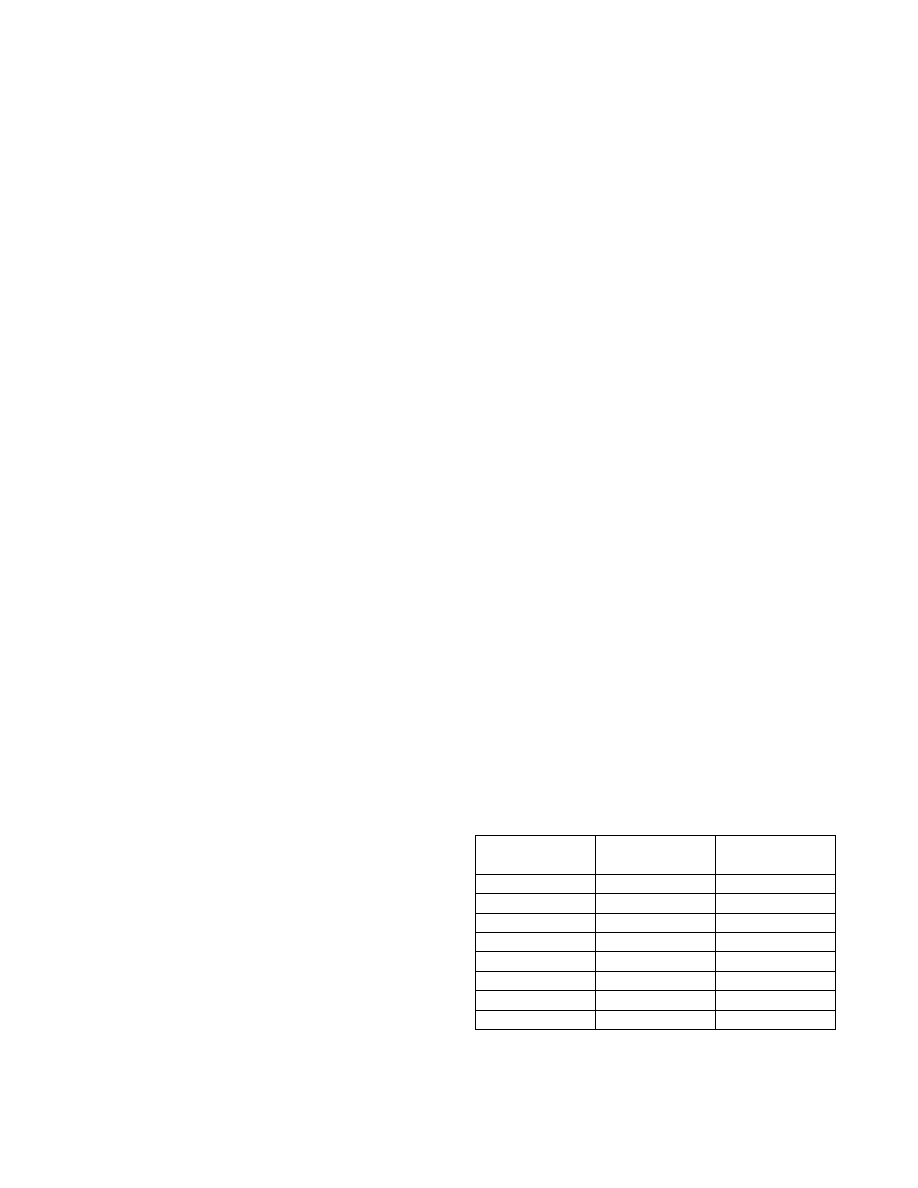
In crossover-disabled mode, the thresholds between
coarse and fine mode are a function of the number of
right-shifts being used. With the use of right-shifting,
the fine-mode full scale is programmed to (1/2n) of the
coarse-mode full scale. The device now automatically
ranges to choose the range that gives the best resolution
for the measurement. Table 4 shows the threshold values
for each possible number of right-shifts.
Low-Voltage Operation
The device contains two power-on reset (POR) levels.
The lower level is a digital POR (POD) and the higher
level is an analog POR (POA). At startup, before the sup-
ply voltage rises above POA, the outputs are disabled,
all SRAM locations are set to their defaults, shadowed
EEPROM (SEE) locations are zero, and all analog cir-
cuitry is disabled. When VCC reaches POA, the SEE is
recalled, and the analog circuitry is enabled. While VCC
remains above POA, the device is in its normal operating
state, and it responds based on its nonvolatile configu-
ration. If during operation VCC falls below POA, but is
still above POD, the SRAM retains the SEE settings from
the first SEE recall, but the device analog is shut down
and the outputs disabled. If the supply voltage recovers
back above POA, the device immediately resumes nor-
mal operation. If the supply voltage falls below POD, the
device SRAM is placed in its default state and another
SEE recall is required to reload the nonvolatile settings.
The EEPROM recall occurs the next time VCC next
exceeds POA. Figure 7 shows the sequence of events
as the voltage varies.
Table 4. RSSI1/RSSI2 Hysteresis
Threshold Values
*This is the minimum reported coarse-mode conversion.
NO. OF RIGHT-
SHIFTS
FINE MODE
MAX (HEX)
COARSE MODE
MIN* (HEX)
0
FFF8
F000
1
7FFC
7800
2
3FFE
3C00
3
1FFF
1E00
4
0FFF
0F00
5
07FF
0780
6
03FF
03C0
7
01FF
01E0
相關(guān)PDF資料 |
PDF描述 |
|---|---|
| DS1878T+T&R | IC CTLR SFP W/DGTL LDD RX 28TQFN |
| DS1881Z-050+T&R | IC DGTL POT NV 2CH 45K 16-SOIC |
| DS1882Z-050+T&R | IC POT DIGIT DL LOG 50K 16SOIC |
| DS1884AT+T | IC SFP PON ONU CTRLR 24TQFN |
| DS2105Z+ | IC SCSI TERMINATOR 16-SOIC |
相關(guān)代理商/技術(shù)參數(shù) |
參數(shù)描述 |
|---|---|
| DS1878 | 制造商:MAXIM 制造商全稱:Maxim Integrated Products 功能描述:SFP+ Controller with Digital LDD Interface |
| DS1878T | 功能描述:ADC / DAC多通道 SFP+ Controller w/ MAX3946&3945 RoHS:否 制造商:Texas Instruments 轉(zhuǎn)換速率: 分辨率:8 bit 接口類型:SPI 電壓參考: 電源電壓-最大:3.6 V 電源電壓-最小:2 V 最大工作溫度:+ 85 C 安裝風(fēng)格:SMD/SMT 封裝 / 箱體:VQFN-40 |
| DS1878T TR | 制造商:MAXIM 制造商全稱:Maxim Integrated Products 功能描述:SFP+ Controller with Digital LDD Interface |
| DS1878T+ | 功能描述:ADC / DAC多通道 SFP+ Controller w/ MAX3946&3945 RoHS:否 制造商:Texas Instruments 轉(zhuǎn)換速率: 分辨率:8 bit 接口類型:SPI 電壓參考: 電源電壓-最大:3.6 V 電源電壓-最小:2 V 最大工作溫度:+ 85 C 安裝風(fēng)格:SMD/SMT 封裝 / 箱體:VQFN-40 |
| DS1878T+T | 功能描述:ADC / DAC多通道 SFP+ Controller w/ MAX3946&3945 RoHS:否 制造商:Texas Instruments 轉(zhuǎn)換速率: 分辨率:8 bit 接口類型:SPI 電壓參考: 電源電壓-最大:3.6 V 電源電壓-最小:2 V 最大工作溫度:+ 85 C 安裝風(fēng)格:SMD/SMT 封裝 / 箱體:VQFN-40 |
發(fā)布緊急采購(gòu),3分鐘左右您將得到回復(fù)。