- 您現(xiàn)在的位置:買賣IC網(wǎng) > PDF目錄1913 > DS1876T+T&R (Maxim Integrated Products)IC CTRLR SFP DUAL LDD 28TQFN PDF資料下載
參數(shù)資料
| 型號(hào): | DS1876T+T&R |
| 廠商: | Maxim Integrated Products |
| 文件頁數(shù): | 67/69頁 |
| 文件大?。?/td> | 0K |
| 描述: | IC CTRLR SFP DUAL LDD 28TQFN |
| 產(chǎn)品培訓(xùn)模塊: | Lead (SnPb) Finish for COTS Obsolescence Mitigation Program |
| 標(biāo)準(zhǔn)包裝: | 2,500 |
| 類型: | SFP 激光控制器 |
| 輸入類型: | 邏輯 |
| 輸出類型: | 邏輯 |
| 接口: | I²C |
| 電流 - 電源: | 10mA |
| 安裝類型: | 表面貼裝 |
| 封裝/外殼: | 28-WFQFN 裸露焊盤 |
| 供應(yīng)商設(shè)備封裝: | 28-TQFN-EP(5x5) |
| 包裝: | 帶卷 (TR) |
第1頁第2頁第3頁第4頁第5頁第6頁第7頁第8頁第9頁第10頁第11頁第12頁第13頁第14頁第15頁第16頁第17頁第18頁第19頁第20頁第21頁第22頁第23頁第24頁第25頁第26頁第27頁第28頁第29頁第30頁第31頁第32頁第33頁第34頁第35頁第36頁第37頁第38頁第39頁第40頁第41頁第42頁第43頁第44頁第45頁第46頁第47頁第48頁第49頁第50頁第51頁第52頁第53頁第54頁第55頁第56頁第57頁第58頁第59頁第60頁第61頁第62頁第63頁第64頁第65頁第66頁當(dāng)前第67頁第68頁第69頁
7
Maxim Integrated
SFP Controller with Dual LDD Interface
DS1876
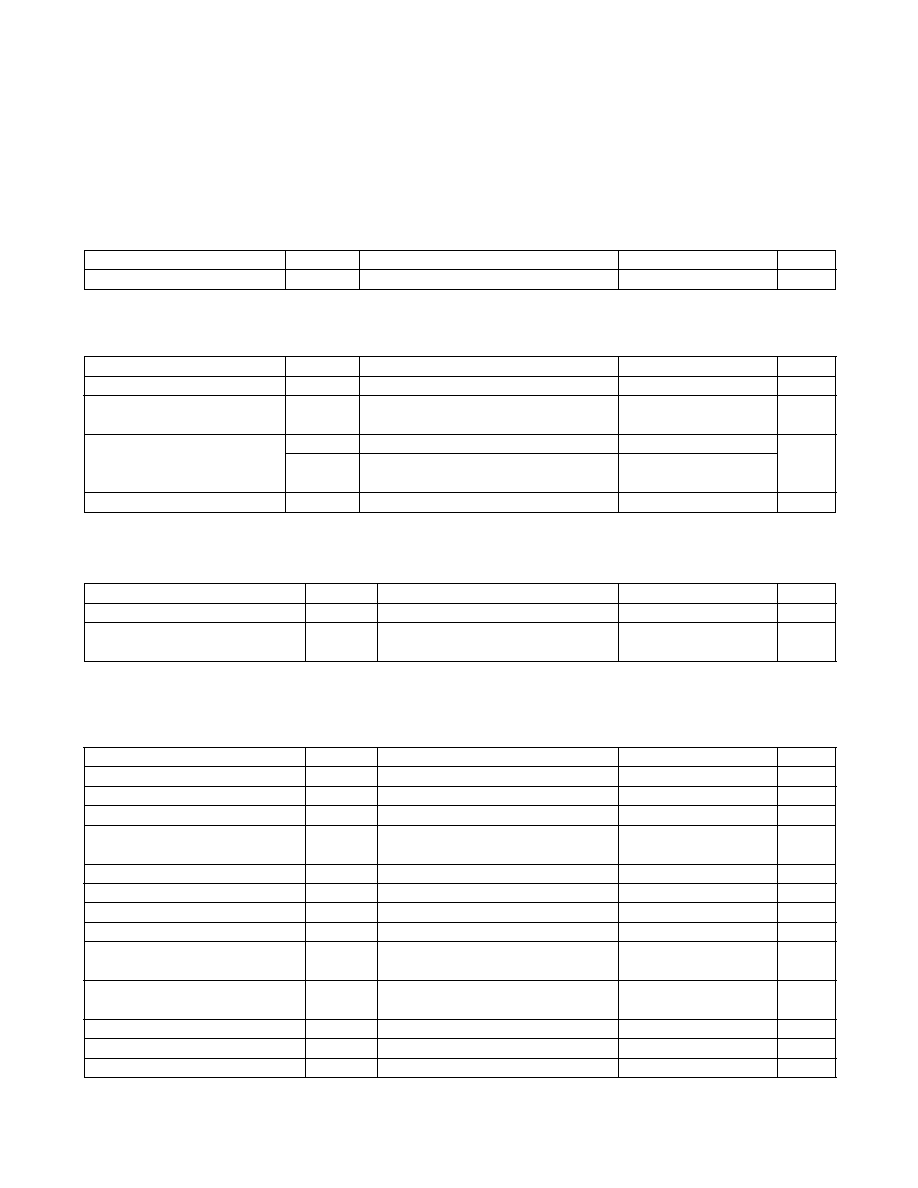
DIGITAL THERMOMETER CHARACTERISTICS
(VCC = +2.85V to +3.9V, TA = -40NC to +95NC, unless otherwise noted.)
AC ELECTRICAL CHARACTERISTICS
(VCC = +2.85V to +3.9V, TA = -40NC to +95NC, unless otherwise noted.)
QUICK-TRIP TIMING CHARACTERISTICS
(VCC = +2.85V to +3.9V, TA = -40NC to +95NC, unless otherwise noted.)
I2C AC ELECTRICAL CHARACTERISTICS
(VCC = +2.85V to +3.9V, TA = -40NC to +95NC, timing referenced to VIL(MAX) and VIH(MIN), unless otherwise noted. See the I2C
Communication section.)
PARAMETER
SYMBOL
CONDITIONS
MIN
TYP
MAX
UNITS
Thermometer Error
TERR
-40NC to +95NC
-3
+3
N
C
PARAMETER
SYMBOL
CONDITIONS
MIN
TYP
MAX
UNITS
TXD_ Enable
tOFF
From ↑ TXD_
5
F
s
Recovery from TXD_ Disable
(Figure 2)
tON
From ↑ TXD_
1
ms
Fault Reset Time (to TXFOUT = 0)
tINITR1
From ↑ TXD_
131
ms
tINITR2
On power-up or ↑ TXD_, when VCC LO
alarm is detected (Note 5)
161
Fault Assert Time (to TXFOUT = 1)
tFAULT
After HTXP_, LTXP_, HBATH_
1.6
10.5
F
s
PARAMETER
SYMBOL
CONDITIONS
MIN
TYP
MAX
UNITS
Output-Enable Time Following POA
tINIT
20
ms
Sample Time per Quick-Trip
Comparison
tREP
1.6
F
s
PARAMETER
SYMBOL
CONDITIONS
MIN
TYP
MAX
UNITS
SCL Clock Frequency
fSCL
(Note 6)
0
400
kHz
Clock Pulse-Width Low
tLOW
1.3
F
s
Clock Pulse-Width High
tHIGH
0.6
F
s
Bus Free Time Between STOP and
START Condition
tBUF
1.3
F
s
START Hold Time
tHD:STA
0.6
F
s
START Setup Time
tSU:STA
0.6
F
s
Data Out Hold Time
tHD:DAT
0
0.9
F
s
Data In Setup Time
tSU:DAT
100
ns
Rise Time of Both SDA and SCL
Signals
tR
(Note 7)
20 +
0.1CB
300
ns
Fall Time of Both SDA and SCL
Signals
tF
(Note 7)
20 +
0.1CB
300
ns
STOP Setup Time
tSU:STO
0.6
F
s
Capacitive Load for Each Bus Line
CB
400
pF
EEPROM Write Time
tWR
(Note 8)
20
ms
相關(guān)PDF資料 |
PDF描述 |
|---|---|
| DS1877T+T&R | IC CTLR/MON SFP 1-2CH 28TQFN |
| DS1878T+T&R | IC CTLR SFP W/DGTL LDD RX 28TQFN |
| DS1881Z-050+T&R | IC DGTL POT NV 2CH 45K 16-SOIC |
| DS1882Z-050+T&R | IC POT DIGIT DL LOG 50K 16SOIC |
| DS1884AT+T | IC SFP PON ONU CTRLR 24TQFN |
相關(guān)代理商/技術(shù)參數(shù) |
參數(shù)描述 |
|---|---|
| DS1877 | 制造商:MAXIM 制造商全稱:Maxim Integrated Products 功能描述:SFP Controller for Dual Rx Interface |
| DS1877T+ | 功能描述:ADC / DAC多通道 SFP+ Controller w/ Dual RX Interface RoHS:否 制造商:Texas Instruments 轉(zhuǎn)換速率: 分辨率:8 bit 接口類型:SPI 電壓參考: 電源電壓-最大:3.6 V 電源電壓-最小:2 V 最大工作溫度:+ 85 C 安裝風(fēng)格:SMD/SMT 封裝 / 箱體:VQFN-40 |
| DS1877T+T&R | 制造商:Maxim Integrated Products 功能描述:SFP CTRLR FOR DUAL RX INTERFACE TQF - Tape and Reel 制造商:Maxim Integrated Products 功能描述:IC CTLR/MON SFP 1-2CH 28TQFN |
| DS1877T+T&R | 功能描述:ADC / DAC多通道 SFP+ Controller w/ Dual RX Interface RoHS:否 制造商:Texas Instruments 轉(zhuǎn)換速率: 分辨率:8 bit 接口類型:SPI 電壓參考: 電源電壓-最大:3.6 V 電源電壓-最小:2 V 最大工作溫度:+ 85 C 安裝風(fēng)格:SMD/SMT 封裝 / 箱體:VQFN-40 |
| DS1877T+TR | 制造商:MAXIM 制造商全稱:Maxim Integrated Products 功能描述:SFP Controller for Dual Rx Interface |
發(fā)布緊急采購,3分鐘左右您將得到回復(fù)。