- 您現(xiàn)在的位置:買賣IC網(wǎng) > PDF目錄374035 > ADSP-2173BS-80 (ANALOG DEVICES INC) DSP Microcomputer PDF資料下載
參數(shù)資料
| 型號: | ADSP-2173BS-80 |
| 廠商: | ANALOG DEVICES INC |
| 元件分類: | 數(shù)字信號處理 |
| 英文描述: | DSP Microcomputer |
| 中文描述: | 24-BIT, 10 MHz, OTHER DSP, PQFP128 |
| 封裝: | PLASTIC, QFP-128 |
| 文件頁數(shù): | 40/52頁 |
| 文件大小: | 664K |
| 代理商: | ADSP-2173BS-80 |
第1頁第2頁第3頁第4頁第5頁第6頁第7頁第8頁第9頁第10頁第11頁第12頁第13頁第14頁第15頁第16頁第17頁第18頁第19頁第20頁第21頁第22頁第23頁第24頁第25頁第26頁第27頁第28頁第29頁第30頁第31頁第32頁第33頁第34頁第35頁第36頁第37頁第38頁第39頁當(dāng)前第40頁第41頁第42頁第43頁第44頁第45頁第46頁第47頁第48頁第49頁第50頁第51頁第52頁
REV. A
–40–
ADSP-2171/ADSP-2172/ADSP-2173
ADSP-2173
Parameter
Min
Max
Unit
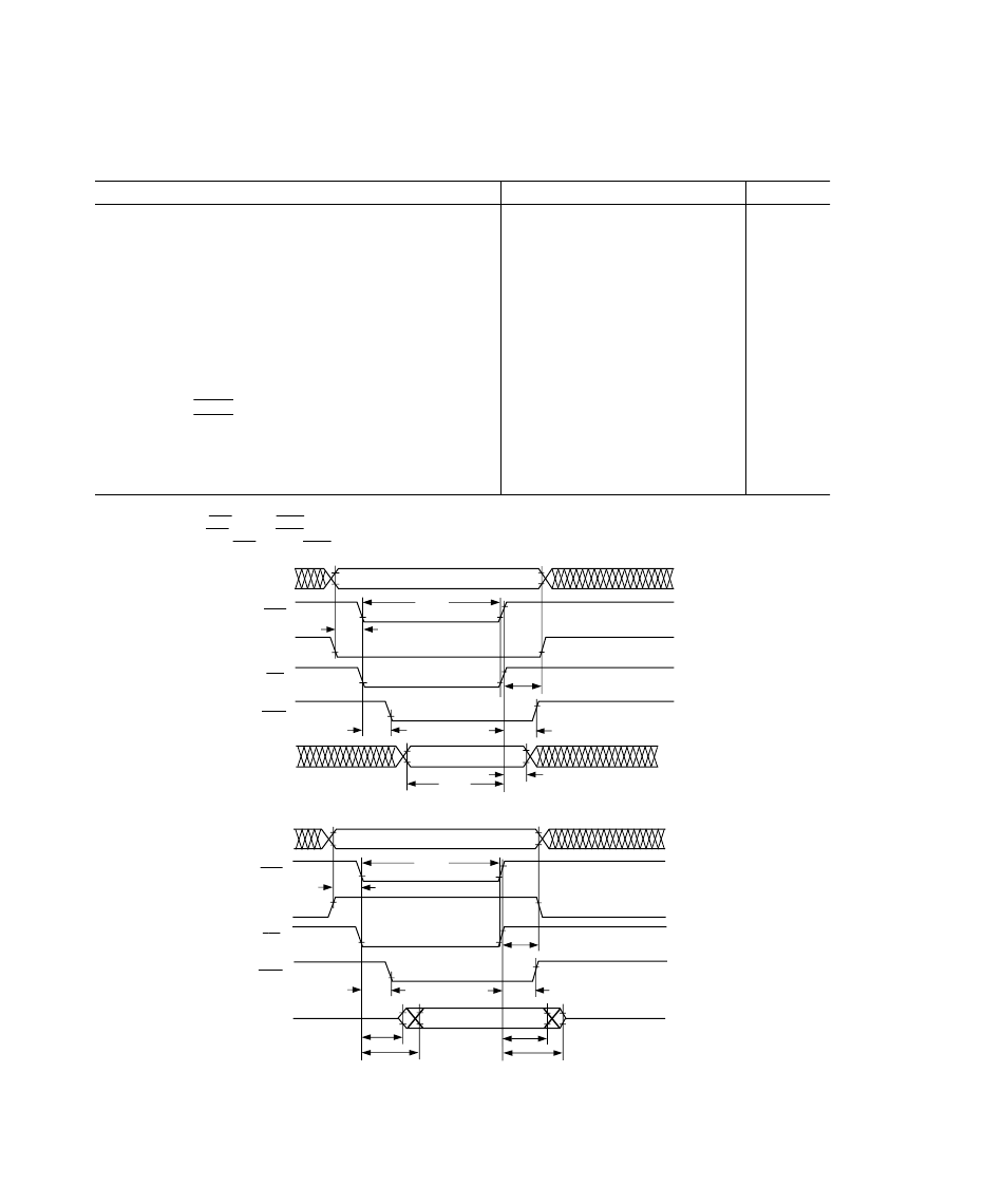
Host Interface Port
Separate Data and Address (HMD1 = 0)
Read Strobe and Write Strobe (HMD0 = 1)
T iming Requirement:
t
HSU
t
HDSU
t
HWDH
t
HH
t
HRWP
HA2–0, HRW Setup before Start of Write or Read
1
Data Setup before End of Write
2
Data Hold after End of Write
2
HA2–0, HRW Hold after End of Write or Read
2
Read or Write Pulse Width
3
8
8
3
3
30
ns
ns
ns
ns
ns
Switching Characteristic:
t
HSHK
t
HK H
t
HDE
t
HDD
t
HRDH
t
HRDD
HACK
Low after Start of Write or Read
1
HACK
Hold after End of Write or Read
2
Data Enabled after Start of Read
1
Data Valid after Start of Read
1
Data Hold after End of Read
2
Data Disabled after End of Read
2
0
0
0
20
20
ns
ns
ns
ns
ns
ns
23
0
15
NOT ES
1
Start of Write or Read =
HDS
Low and
HSEL
Low.
2
End of Write or Read =
HDS
High and
HSEL
High.
3
Read or Write Pulse Width =
HDS
Low and
HSEL
Low.
DATA
HD15–0
HSEL
HRW
HACK
HA2–0
ADDRESS
t
HSU
t
HH
t
HWDH
t
HRWP
t
HSHK
t
HKH
t
HDSU
HDS
DATA
HD15–0
HSEL
HDS
HACK
HA2–0
ADDRESS
t
HSU
t
HH
t
HRWP
t
HRDH
t
HRDD
t
HKH
t
HSHK
t
HDE
t
HDD
HRW
Figure 31. Host Interface Port (HMD1 = 0, HMD0 = 1)
Host Write Cycle
Host Read Cycle
相關(guān)PDF資料 |
PDF描述 |
|---|---|
| ADSP-2171 | DSP Microcomputer(DSP 微計(jì)算機(jī)) |
| ADSP-2172 | DSP Microcomputer(DSP 微計(jì)算機(jī)) |
| ADSP-2173 | DSP Microcomputer(DSP 微計(jì)算機(jī)) |
| ADSP-2181BS-115 | DSP Microcomputer |
| ADSP-2181BS-133 | DSP Microcomputer |
相關(guān)代理商/技術(shù)參數(shù) |
參數(shù)描述 |
|---|---|
| ADSP-2173BST-80 | 制造商:Analog Devices 功能描述:DSP Fixed-Point 16-Bit 20MHz 20MIPS 128-Pin TQFP 制造商:Rochester Electronics LLC 功能描述:16BIT FXD PT PROC 3.3V - Bulk |
| ADSP-2176-760040 | 制造商:Analog Devices 功能描述: |
| ADSP-2176-760061 | 制造商:Analog Devices 功能描述: |
| ADSP-2176-760243 | 制造商:Analog Devices 功能描述: |
| ADSP-2178-780244 | 制造商:AD 制造商全稱:Analog Devices 功能描述:GSM Baseband Processing Chipset |
發(fā)布緊急采購,3分鐘左右您將得到回復(fù)。