- 您現(xiàn)在的位置:買賣IC網(wǎng) > PDF目錄374023 > ADP3801 (Analog Devices, Inc.) High Frequency Switch Mode Dual Li-Ion Battery Chargers(高頻開關(guān)模式雙鋰離子充電器) PDF資料下載
參數(shù)資料
| 型號: | ADP3801 |
| 廠商: | Analog Devices, Inc. |
| 元件分類: | 基準(zhǔn)電壓源/電流源 |
| 英文描述: | High Frequency Switch Mode Dual Li-Ion Battery Chargers(高頻開關(guān)模式雙鋰離子充電器) |
| 中文描述: | 高頻開關(guān)雙鋰離子電池充電器(高頻開關(guān)模式雙鋰離子充電器) |
| 文件頁數(shù): | 18/20頁 |
| 文件大?。?/td> | 278K |
| 代理商: | ADP3801 |
ADP3801/ADP3802
–18–
REV. 0
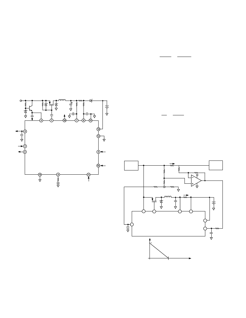
VCC Greater Than 20 V Operation
Some ac/dc adapters have a poorly regulated output voltage
that can rise above the 20 V maximum operating voltage of the
ADP3801/ADP3802. The circuit in Figure 34 uses a Zener
diode and an NPN transistor to extend the ADP3801/ADP3802’s
maximum input voltage. The Zener should be at least 3 V higher
than the final battery voltage to meet the minimum headroom
requirements. 3 V is used to account for the V
BE
drop of the
2N3904 transistor and additional losses in the circuit. If V
IN
drops below the value of the Zener diode, VCC is no longer
regulated and it tracks V
IN
. If the 2 V of headroom on the cur-
rent sense pins is not maintained, then the circuits of Figures 32
and 33 can also be used in conjunction with the circuit of Figure
34.
VCC
DRV
EOC
CS–
CS+
ISET
BATA
BAT
ADJ
GND
RESET
V
IN
VL
100k
V
2N3904
ADP3801/ADP3802
SD
0.1
m
F
0.1
m
F
BATB
10k
V
9V
3.3V
33
m
H
40m
V
9V
A/B
COMP
140
m
F
PROG
Figure 34. VCC Greater Than 20 V Operation
The gate drive of the PFET is capacitively coupled to the DRV
pin with a 0.1
μ
F capacitor. While the DRV pin is switching, the
voltage swing on the DRV pin is coupled to the gate, but the dc
voltage is blocked. This allows the gate of the PFET to be at a
voltage that is higher than the absolute maximum rating of the
DRV pin. The 9 V Zener diode limits the gate drive voltage and
the 100 k
resistor provides a dc pull-up to turn the PFET off
when the DRV pin is not switching.
System Current Sense Reduces Charge Current
In many applications the power required for the system and the
battery charger exceeds the total power available from the ac/dc
adapter. A design where battery charger current is decreased as
the system current increases helps to keep a constant power
demand on the brick. Dynamically adjusting the charge current
keeps the total power output of the brick constant. The circuit
in Figure 35 uses an external low cost amplifier to sense the
system current and dynamically control the ADP3801/ADP3802’s
charge current.
The current setting voltage is produced by R3 and R4 according
to the following formula:
I
R
R
R
R
VL
SET
CS
≈
×
+
1
10
3
3
4
This equation is approximate because the impedance of R2 and
R1 does effect the resistor divider of R3 and R4, but the impact
is small. As the system current increases, the voltage across R
SS
also increases. This voltage is subtracted from V
ISET
with a gain
set by R1 and R2. As the graph in Figure 35 shows, the charge
current reduces as the system current increases, and eventually
the charge current becomes zero (I
ZERO
). The system current at
which this occurs can be set by selecting R1 and R2 according
to the following formula:
I
R
R
R
R
ISET
ZERO
CS
SS
≈
×
×
1
2
10
Because the AD8531 is a single supply amplifier with its nega-
tive rail at ground, its output does not go below 0.0 V, so any
further increase in system current does not change V
ISET
. De-
signing a charger with a maximum charge current of 3A (R
CS
=
0.05
) which reduces to zero when the system current reaches
7A (R
SS
= 0.025
) results in the following resistor values: R1 =
100 k
, R2 = 820 k
, R3 = 8.3 k
, R4 = 10 k
.
VCC
DRV
CS–
CS+
ISET
V
BAT
BAT
VL
0.1
m
F
R
SS
ADP3801/ADP3802
I
BAT
AC/DC
BRICK
R3
8.3k
V
SYSTEM
VCC
R4
10k
V
R1
100k
V
I
SYSTEM
R2
820k
V
R2
820k
V
R1
100k
V
R
CS
100k
V
I
ZERO
(I
SET
) = MAXIMUM CHARGE CURRENT
I
BAT
0
0
I
SYSTEM
OP193
Figure 35. System Current Sense Reduces Charge Current
相關(guān)PDF資料 |
PDF描述 |
|---|---|
| ADP3802 | High Frequency Switch Mode Dual Li-Ion Battery Chargers(高頻開關(guān)模式雙鋰離子充電器) |
| ADP3804JRU-125 | Aluminum Electrolytic Radial Leaded Bi-Polar Capacitor; Capacitance: 220uF; Voltage: 35V; Case Size: 12.5x20 mm; Packaging: Bulk |
| ADP3804JRU-126 | Aluminum Electrolytic Radial Leaded Bi-Polar Capacitor; Capacitance: 330uF; Voltage: 35V; Case Size: 12.5x20 mm; Packaging: Bulk |
| ADP3804 | Secondary Over-Voltage Protection for 2-4 cell in series Li-Ion/Poly (4.50V) 8-TSSOP -40 to 110 |
| ADP3804JRU | Secondary Over-Voltage Protection for 2-4 cell in series Li-Ion/Poly (4.50V) 8-TSSOP -40 to 110 |
相關(guān)代理商/技術(shù)參數(shù) |
參數(shù)描述 |
|---|---|
| ADP38010001RR | 制造商:Rochester Electronics LLC 功能描述:- Bulk |
| ADP3801AR | 制造商:Analog Devices 功能描述: |
| ADP3801AR-REEL | 制造商:Rochester Electronics LLC 功能描述:SWITCH MODE DUAL CHARGER/LDO REGULATOR - Tape and Reel |
| ADP3802 | 制造商:AD 制造商全稱:Analog Devices 功能描述:High Frequency Switch Mode Dual Li-Ion Battery Chargers |
| ADP3802AR | 制造商:AD 制造商全稱:Analog Devices 功能描述:High Frequency Switch Mode Dual Li-Ion Battery Chargers |
發(fā)布緊急采購,3分鐘左右您將得到回復(fù)。