- 您現(xiàn)在的位置:買賣IC網 > PDF目錄373980 > ADE7169ASTF16-RL (ANALOG DEVICES INC) Single-Phase Energy Measurement IC with 8052 MCU, RTC and LCD driver PDF資料下載
參數(shù)資料
| 型號: | ADE7169ASTF16-RL |
| 廠商: | ANALOG DEVICES INC |
| 元件分類: | 模擬信號調理 |
| 英文描述: | Single-Phase Energy Measurement IC with 8052 MCU, RTC and LCD driver |
| 中文描述: | ANALOG CIRCUIT, PQFP64 |
| 封裝: | MS-026BCD, LQFP-64 |
| 文件頁數(shù): | 26/140頁 |
| 文件大小: | 1359K |
| 代理商: | ADE7169ASTF16-RL |
第1頁第2頁第3頁第4頁第5頁第6頁第7頁第8頁第9頁第10頁第11頁第12頁第13頁第14頁第15頁第16頁第17頁第18頁第19頁第20頁第21頁第22頁第23頁第24頁第25頁當前第26頁第27頁第28頁第29頁第30頁第31頁第32頁第33頁第34頁第35頁第36頁第37頁第38頁第39頁第40頁第41頁第42頁第43頁第44頁第45頁第46頁第47頁第48頁第49頁第50頁第51頁第52頁第53頁第54頁第55頁第56頁第57頁第58頁第59頁第60頁第61頁第62頁第63頁第64頁第65頁第66頁第67頁第68頁第69頁第70頁第71頁第72頁第73頁第74頁第75頁第76頁第77頁第78頁第79頁第80頁第81頁第82頁第83頁第84頁第85頁第86頁第87頁第88頁第89頁第90頁第91頁第92頁第93頁第94頁第95頁第96頁第97頁第98頁第99頁第100頁第101頁第102頁第103頁第104頁第105頁第106頁第107頁第108頁第109頁第110頁第111頁第112頁第113頁第114頁第115頁第116頁第117頁第118頁第119頁第120頁第121頁第122頁第123頁第124頁第125頁第126頁第127頁第128頁第129頁第130頁第131頁第132頁第133頁第134頁第135頁第136頁第137頁第138頁第139頁第140頁
ADE7169F16
Preliminary Technical Data
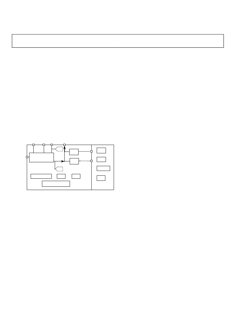
V
SWOUT
output pin reflects the voltage at V
SW
, and has a
maximum output current of TBD mA. This pin may also be
used to power a limited number of peripheral components. The
2.5V analog supply, V
INTA
and the 2.5V supply for the core logic,
V
INTD
, are derived by on-chip linear regulators from V
SW
. Figure
9 shows the power supply architecture of ADE7169F16.
Rev. PrD | Page 26 of 140
The ADE7169F16 provides automatic battery switchover
between V
DD
and V
BAT
based on the voltage level detected at V
DD
or V
DCIN
. Additionally, the BCTRL input can also be used to
trigger a battery switchover. The conditions for switching V
SW
from V
DD
to V
BAT
and back to V
DD
are described in the Battery
Switchover section.
V
DCIN
is an input pin that can be connected to a 0V to 3.3V DC
signal. This input is intended for power supply supervisory
purposes and does not provide power to the ADE7169F16
circuitry - see Battery Switchover section.
MCU
SCRATCHPAD
LCD
RTC
TEMPERATURE ADC
DCIN
V
DD
V
INTD
V
INTA
V
3.3V
2.5V
LDO
BAT
V
SWOUT
V
BCTRL
SW
V
ADE
SPI/I2C
UART
LDO
POWER SUPPLY
MANAGEMENT
ADC
ADC
Figure 9: Power Supply Architecture
BATTERY SWITCHOVER
ADE7169F16 monitors V
DD
, V
BAT
, and V
DCIN
. Automatic
battery switchover from V
DD
to V
BAT
can be configured based on
the status of V
DD
, V
DCIN
, or the BCTRL pin. Battery switchover is
enabled by default. Setting bit 1 in the Battery Switchover
Configuration SFR (BATPR, 0xF5), disables battery switchover
so that V
DD
is always connected to V
SW
. The source of V
SW
is
indicated by bit 6 in the Peripheral Configuration SFR
(PERIPH, 0xF4), which is set when V
SW
is connected to V
DD
and
cleared when V
SW
is connected to V
BAT
.
The battery switchover functionality provided by the
ADE7169F16 allows a seamless transition from V
DD
to V
BAT
. An
automatic battery switchover option ensures a stable power
supply to the ADE7169F16, as long as the external battery
voltage is above TBD V. It allows continuous code execution
even while the internal power supply is switching from V
DD
to
V
BAT
and back. Note that the energy metering ADCs are not
available when V
BAT
is being used for V
SW
.
Power supply monitor (PSM) interrupts can be enabled to
indicate when battery switchover occurs and when the V
DD
power supply is restored - see the Power Supply Monitor
Interrupt (PSM) section.
Switching from V
DD
to V
BAT
There are three events that can be enabled to switch the internal
power supply, V
SW
, from V
DD
to V
BAT
:
1.
(V
DCIN
< 1.2 V):
When V
DCIN
falls below 1.2V V
SW
switches from V
DD
to V
BAT
. This event is enabled
when the BATTPROG[1:0] bits in the Battery
Switchover Configuration SFR (BATPR, 0xF5) are
clear. Setting this bit will disable switchover based on
V
DCIN
. Battery switchover on low V
DCIN
is disabled by
default.
2.
(V
DD
< TBD V):
When V
DD
falls below TBD V V
SW
switches from V
DD
to V
BAT
. This event is enabled
when BATTPROG[1] in the Battery Switchover
Configuration SFR (BATPR, 0xF5) is cleared.
3.
Rising edge on BCTRL:
When the battery control
pin, BCTRL, goes high, V
SW
switches from V
DD
to
V
BAT
. This external switchover signal can trigger a
switchover to V
BAT
at any time. Setting bits
INT1PRG[4:2] to 0bx01 in the Interrupt pins
configuration SFR (INTPR, 0xFF) enables the battery
control pin.
Switching from V
BAT
to V
DD
To switch V
SW
back from V
BAT
to V
DD
all of the events that are
enabled to force battery switchover must be false:
1.
(V
DCIN
< 1.2 V) and (V
DD
< TBD V) Enabled:
If the
low V
DCIN
condition is enabled, V
SW
switches to V
DD
after V
DCIN
remains above TBD V for TBD seconds
and V
DD
remains above TBD V for TBD seconds.
2.
(V
DD
< TBD V) Enabled:
V
SW
switches back to V
DD
after V
DD
has been above TBD V for TBD seconds.
3.
BCTRL Enabled:
V
SW
switches back to V
DD
after
BCTRL is low and number 1 or number 2 are satisfied.
POWER SUPPLY MONITOR INTERRUPT (PSM)
The Power Supply Monitor Interrupt (PSM) alerts the 8052 core
of power supply events. The PSM interrupt is disabled by
default. Setting the EPSM bit in the Interrupt Enable and
Priority 2 SFR (IEIP2, 0xA9) enables the PSM interrupt. The
Power Management Interrupt Enable SFR (IPSME, 0xEC)
controls the events that result in a PSM interrupt. Figure 10 is a
diagram illustrating how the PSM interrupt vector is shared
among the PSM interrupt sources. The PSM interrupt flags are
latched and must be cleared by writing to the flag register.
相關PDF資料 |
PDF描述 |
|---|---|
| ADE7169ASTZF16 | Single-Phase Energy Measurement IC with 8052 MCU, RTC and LCD driver |
| ADE7169ASTZF16-RL | Single-Phase Energy Measurement IC with 8052 MCU, RTC and LCD driver |
| ADE7169F16 | Single-Phase Energy Measurement IC with 8052 MCU, RTC and LCD driver |
| ADE7751 | Energy Metering IC with On-Chip Fault Detection |
| ADE7751AAN-REF | Energy Metering IC with On-Chip Fault Detection |
相關代理商/技術參數(shù) |
參數(shù)描述 |
|---|---|
| ADE7169ASTZF16 | 功能描述:IC ENERGY METER 1PHASE 64LQFP RoHS:是 類別:集成電路 (IC) >> PMIC - 能量測量 系列:- 產品培訓模塊:Lead (SnPb) Finish for COTS Obsolescence Mitigation Program 標準包裝:2,500 系列:* |
| ADE7169ASTZF16-RL | 功能描述:IC ENERGY METER 1PHASE 64LQFP RoHS:是 類別:集成電路 (IC) >> PMIC - 能量測量 系列:- 產品培訓模塊:Lead (SnPb) Finish for COTS Obsolescence Mitigation Program 標準包裝:2,500 系列:* |
| ADE7169F16 | 制造商:AD 制造商全稱:Analog Devices 功能描述:Single-Phase Energy Measurement IC with 8052 MCU, RTC and LCD driver |
| ADE75 | 制造商:AD 制造商全稱:Analog Devices 功能描述:Single-Phase Energy Measurement IC with 8052 MCU, RTC and LCD driver |
| ADE7518ASTZF16 | 功能描述:IC ENERGY METER MCU 16K 64LQFP RoHS:是 類別:集成電路 (IC) >> PMIC - 能量測量 系列:- 產品培訓模塊:Lead (SnPb) Finish for COTS Obsolescence Mitigation Program 標準包裝:2,500 系列:* |
發(fā)布緊急采購,3分鐘左右您將得到回復。