- 您現(xiàn)在的位置:買(mǎi)賣(mài)IC網(wǎng) > PDF目錄97841 > AD8343ARUZ-REEL (ANALOG DEVICES INC) 0 MHz - 2500 MHz RF/MICROWAVE DOUBLE BALANCED MIXER PDF資料下載
參數(shù)資料
| 型號(hào): | AD8343ARUZ-REEL |
| 廠(chǎng)商: | ANALOG DEVICES INC |
| 元件分類(lèi): | 混頻器 |
| 英文描述: | 0 MHz - 2500 MHz RF/MICROWAVE DOUBLE BALANCED MIXER |
| 封裝: | LEAD FREE, PLASTIC, TSSOP-14 |
| 文件頁(yè)數(shù): | 7/32頁(yè) |
| 文件大小: | 2171K |
| 代理商: | AD8343ARUZ-REEL |
第1頁(yè)第2頁(yè)第3頁(yè)第4頁(yè)第5頁(yè)第6頁(yè)當(dāng)前第7頁(yè)第8頁(yè)第9頁(yè)第10頁(yè)第11頁(yè)第12頁(yè)第13頁(yè)第14頁(yè)第15頁(yè)第16頁(yè)第17頁(yè)第18頁(yè)第19頁(yè)第20頁(yè)第21頁(yè)第22頁(yè)第23頁(yè)第24頁(yè)第25頁(yè)第26頁(yè)第27頁(yè)第28頁(yè)第29頁(yè)第30頁(yè)第31頁(yè)第32頁(yè)
AD8343
Rev. B | Page 15 of 32
CIRCUIT DESCRIPTION
The AD8343 is a mixer intended for high-intercept applications.
The signal paths are entirely differential and dc-coupled to
permit high-performance operation over a broad range of
frequencies; the block diagram (see Figure 1) shows the basic
functional blocks. The bias cell provides a PTAT (proportional
to absolute temperature) bias to the LO driver and core. The LO
driver consists of a three-stage limiting differential amplifier
that provides a very fast (almost square-wave) drive to the bases
of the core transistors.
The AD8343 core utilizes a standard architecture where the
signal inputs are directly applied to the emitters of the transis-
tors in the cell (see Figure 49 and Figure 55). The bases are
driven by the hard-limited LO signal that directs the transistors
to steer the input currents into periodically alternating pairs of
output terminals, thus providing the periodic polarity reversal
that effectively multiplies the signal by a square wave of the LO
frequency.
BIAS
AD8343
VPOS
DCPL
PWDN
LOIP
LOIM
INPP
INPM
OUTP
OUTM
COMM
MIXER
CORE
LO
DRIVER
Q1 Q2
Q3 Q4
4
6
10
9
2
3
12
13
14
11
8
7
1
5
01
03
4-
0
49
Figure 49. Topology
To illustrate this functionality, when LOIP is positive, Q1
and Q4 are turned on, and Q2 and Q3 are turned off. In this
condition, Q1 connects IINPP to OUTM and Q4 connects IINPM
to OUTP. When LOIP is negative, the roles of the transistors
reverse, steering IINPP to OUTP and IINPM to OUTM. Isolation
and gain are possible because, at any instant, the signal passes
through a common-base transistor amplifier pair.
Multiplication is the essence of frequency mixing; an ideal
multiplier would make an excellent mixer. The theory is
expressed in the following trigonometric identity:
sin(ωsigt) × sin(ωLOt) = [cos(ωsigt ωLOt) cos(ωsigt + ωLOt)]
This states that the product of two sine-wave signals of different
frequencies is a pair of sine waves at frequencies equal to the
sum and difference of the two frequencies being multiplied.
Unfortunately, practical implementations of analog multipliers
generally make poor mixers because of imperfect linearity and
the added noise that invariably accompanies attempts to improve
linearity. The best mixers to date are those that use the LO
signal to periodically reverse the polarity of the input signal.
In this class of mixers, frequency conversion occurs as a
result of multiplication of the signal by a square wave at the
LO frequency. Because a square wave contains odd harmonics
in addition to the fundamental, the signal is effectively multi-
plied by each frequency component of the LO. The output of
the mixer therefore contains signals at FLO ± Fsig, 3×FLO ± Fsig,
5× FLO ± Fsig, 7×FLO ± Fsig, etc. The amplitude of the components
arising from signal multiplication by LO harmonics falls off
with increasing harmonic order because the amplitude of a
square wave’s harmonics falls off.
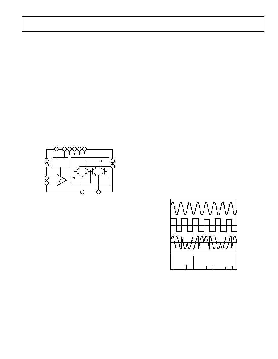
An example of this process is illustrated in Figure 50. The first
pane of this figure shows an 800 MHz sinusoid intended to
represent an input signal. The second pane contains a square
wave representing an LO signal at 600 MHz which has been
hard-limited by the internal LO driver. The third pane shows
the time domain representation of the output waveform and the
fourth pane shows the frequency domain representation. The
two strongest lines in the spectrum are the sum and difference
frequencies arising from multiplication of the signal by the LOs
fundamental frequency. The weaker spectral lines are the result
of the multiplication of the signal by various harmonics of the
LO square wave.
FREQUENCY
DOMAIN
LOCAL
OSCILLATOR
TIME
DOMAIN
SIGNAL
SIG × LO
FREQUENCY
SI
G
–
L
O
SI
G
+
L
O
3×
L
O
–
S
IG
5×
L
O
–
S
IG
3×
L
O
+
S
IG
7×
L
O
–
S
IG
5×
L
O
+
S
IG
01
03
4-
0
50
Figure 50. Signal Switching Characteristics of the AD8343
相關(guān)PDF資料 |
PDF描述 |
|---|---|
| AD8345AREZ1 | 140 MHz - 1000 MHz RF/MICROWAVE QUADRAPHASE MODULATOR |
| AD8345AREZ-RL7 | 140 MHz - 1000 MHz RF/MICROWAVE QUADRAPHASE MODULATOR |
| AD8345AREZ-REEL7 | 140 MHz - 1000 MHz RF/MICROWAVE QUADRAPHASE MODULATOR |
| AD8346ARUZ-REEL | 800 MHz - 2500 MHz RF/MICROWAVE I/Q MODULATOR |
| AD8346ARUZ-REEL7 | 800 MHz - 2500 MHz RF/MICROWAVE I/Q MODULATOR |
相關(guān)代理商/技術(shù)參數(shù) |
參數(shù)描述 |
|---|---|
| AD8343ARUZ-REEL7 | 功能描述:IC MIXER ACTIVE HIGH IP3 14TSSOP RoHS:是 類(lèi)別:RF/IF 和 RFID >> RF 混頻器 系列:AD8343 產(chǎn)品培訓(xùn)模塊:Lead (SnPb) Finish for COTS Obsolescence Mitigation Program 標(biāo)準(zhǔn)包裝:100 系列:- RF 型:W-CDMA 頻率:2.11GHz ~ 2.17GHz 混頻器數(shù)目:1 增益:17dB 噪音數(shù)據(jù):2.2dB 次要屬性:- 電流 - 電源:11.7mA 電源電壓:2.7 V ~ 3.3 V 包裝:托盤(pán) 封裝/外殼:12-VFQFN 裸露焊盤(pán) 供應(yīng)商設(shè)備封裝:12-QFN-EP(3x3) |
| AD8343-EVAL | 制造商:Analog Devices 功能描述:AD8343 EVALUATION BOARD - Bulk |
| AD8343-EVALZ | 制造商:Analog Devices 功能描述:AD8343 EVALUATION BOARD - Bulk |
| AD8344 | 制造商:AD 制造商全稱(chēng):Analog Devices 功能描述:Active Receive Mixer 400 MHz to 1.2 GHz |
| AD8344ACPZ | 制造商:Analog Devices 功能描述:UP/DOWN CONV MIXER 5V 1.2GHZ 16LFCSP EP - Tape and Reel 制造商:Analog Devices 功能描述:IC SM RF MIXER 800MHZ |
發(fā)布緊急采購(gòu),3分鐘左右您將得到回復(fù)。