- 您現(xiàn)在的位置:買賣IC網(wǎng) > PDF目錄294782 > A1280A-CQG172B FPGA, 1232 CLBS, 8000 GATES, 41 MHz, CQFP172 PDF資料下載
參數(shù)資料
| 型號: | A1280A-CQG172B |
| 元件分類: | FPGA |
| 英文描述: | FPGA, 1232 CLBS, 8000 GATES, 41 MHz, CQFP172 |
| 封裝: | CERAMIC, CQFP-172 |
| 文件頁數(shù): | 4/54頁 |
| 文件大?。?/td> | 333K |
| 代理商: | A1280A-CQG172B |
第1頁第2頁第3頁當(dāng)前第4頁第5頁第6頁第7頁第8頁第9頁第10頁第11頁第12頁第13頁第14頁第15頁第16頁第17頁第18頁第19頁第20頁第21頁第22頁第23頁第24頁第25頁第26頁第27頁第28頁第29頁第30頁第31頁第32頁第33頁第34頁第35頁第36頁第37頁第38頁第39頁第40頁第41頁第42頁第43頁第44頁第45頁第46頁第47頁第48頁第49頁第50頁第51頁第52頁第53頁第54頁
RadTolerant FPGAs
1- 8
v3.1
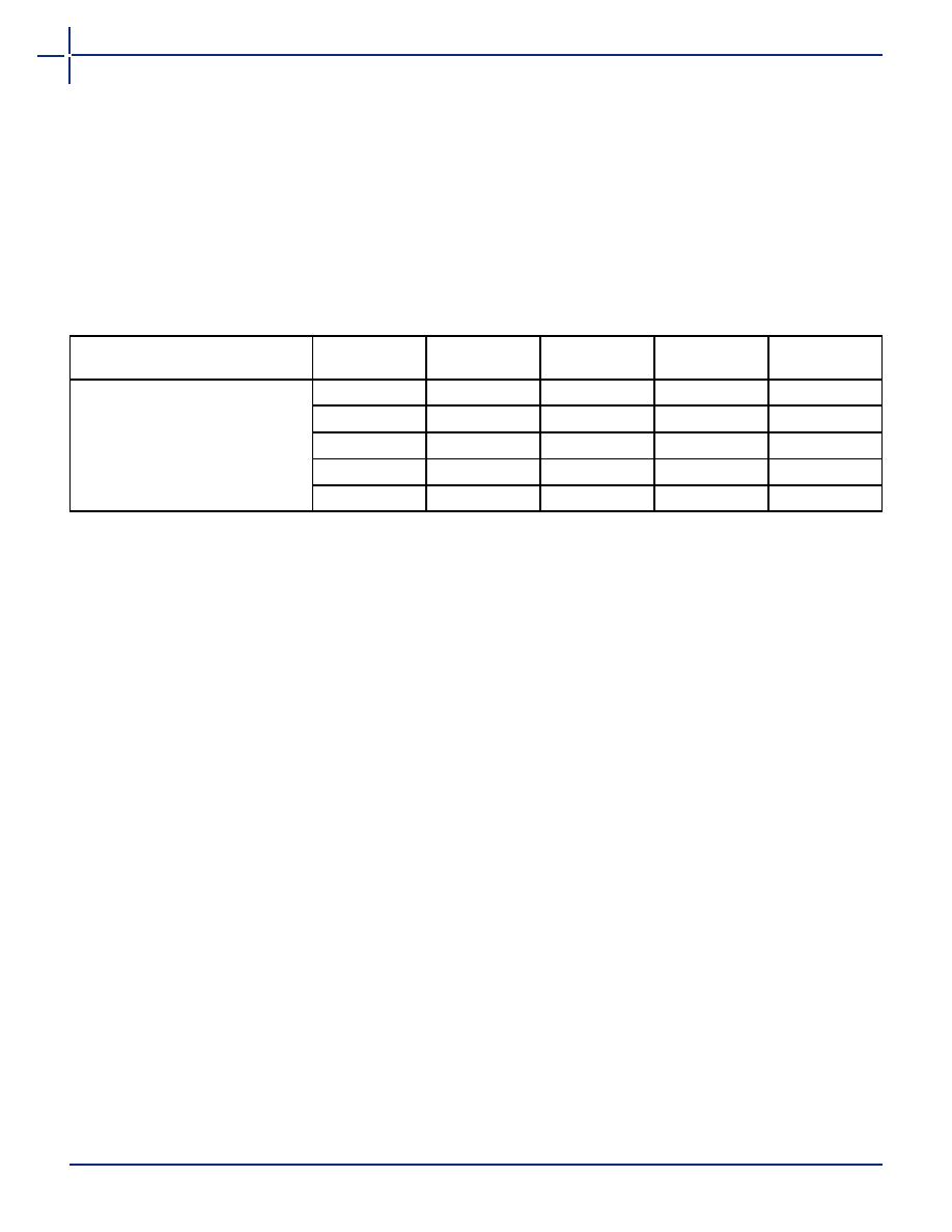
Package Thermal Characteristics
The device junction to case thermal characteristic is
θ
jc,
and the junction to ambient air characteristic is
θ
ja. The
thermal characteristics for
θ
ja are shown with two
different air flow rates.
Maximum junction temperature is 150°C.
A sample calculation of the absolute maximum power
dissipation allowed for a CQFP 172-pin package at
military temperature is as follows:
EQ 1-2
Power Dissipation
General Power Equation
P = [ICCstandby + ICCactive] * VCC + IOL * VOL * N +
IOH * (VCC – VOH) * M
EQ 1-3
where:
ICCstandby is the current flowing when no inputs
or outputs are changing.
ICCactive is the current flowing due to CMOS
switching.
IOL, IOH are TTL sink/source currents.
VOL, VOH are TTL level output voltages.
N equals the number of outputs driving TTL loads
to VOL.
M equals the number of outputs driving TTL loads
to VOH.
Accurate values for N and M are difficult to determine
because they depend on the family type, on design
details, and on the system I/O. The power can be divided
into two components: static and active.
Static Power Component
Actel FPGAs have small static power components that
result in power dissipation lower than that of PALs or
PLDs. By integrating multiple PALs or PLDs into one
FPGA, an even greater reduction in board-level power
dissipation can be achieved.
The power due to standby current is typically a small
component of the overall power. Standby power is
calculated below for commercial, worst-case conditions.
The static power dissipated by TTL loads depends on the
number of outputs driving HIGH or LOW and on the DC
load current. Again, this value is typically small. For
instance, a 32-bit bus sinking 4 mA at 0.33 V will
generate 42 mW with all outputs driving LOW, and
140 mW with all outputs driving HIGH.
Table 1-6 Package Thermal Characteristics
Package Type
Pin Count
θ
jc
θ
ja
Still Air
θ
ja
300 ft./min.
Units
Ceramic Quad Flat Pack
8
7.8
40
30
°C/W
132
7.2
35
25
°C/W
172
6.8
25
20
°C/W
196
6.4
23
15
°C/W
256
6.2
20
10
°C/W
Max. junction temp. (°C) – Max. military temp.
θ
ja
°C/W
()
-----------------------------------------------------------------------------------------------------------------------
150°C – 125°C
25°C/W
---------------------------------------1.0W
==
ICC
VCC
Power
2 mA
5.25 V
10.5 mW
相關(guān)PDF資料 |
PDF描述 |
|---|---|
| A1280A-CQG172M | FPGA, 1232 CLBS, 8000 GATES, 41 MHz, CQFP172 |
| A1020B-CQ84C | FPGA, 547 CLBS, 2000 GATES, 37 MHz, CQFP84 |
| A14100A-1CQ256B | FPGA, 1377 CLBS, 30000 GATES, 100 MHz, CQFP256 |
| A1280A-1CQ172E | FPGA, 1232 CLBS, 8000 GATES, 60 MHz, CQFP172 |
| A1460A-1CQ196E | FPGA, 848 CLBS, 6000 GATES, 100 MHz, CQFP196 |
相關(guān)代理商/技術(shù)參數(shù) |
參數(shù)描述 |
|---|---|
| A1280A-CQG176B | 制造商:MICROSEMI 制造商全稱:Microsemi Corporation 功能描述:ACT 2 Family FPGAs |
| A1280A-CQG176C | 制造商:MICROSEMI 制造商全稱:Microsemi Corporation 功能描述:ACT 2 Family FPGAs |
| A1280A-CQG176I | 制造商:MICROSEMI 制造商全稱:Microsemi Corporation 功能描述:ACT 2 Family FPGAs |
| A1280A-CQG176M | 制造商:MICROSEMI 制造商全稱:Microsemi Corporation 功能描述:ACT 2 Family FPGAs |
| A1280APC160C | 制造商:ACT 功能描述:1280A ACTEL S1A4B |
發(fā)布緊急采購,3分鐘左右您將得到回復(fù)。