- 您現(xiàn)在的位置:買賣IC網(wǎng) > PDF目錄10561 > XRT91L32IQ-F (Exar Corporation)IC TXRX SONET/SDH 8BIT 100QFP PDF資料下載
參數(shù)資料
| 型號(hào): | XRT91L32IQ-F |
| 廠商: | Exar Corporation |
| 文件頁(yè)數(shù): | 3/37頁(yè) |
| 文件大小: | 0K |
| 描述: | IC TXRX SONET/SDH 8BIT 100QFP |
| 標(biāo)準(zhǔn)包裝: | 20 |
| 類型: | 收發(fā)器 |
| 規(guī)程: | SONET/SDH |
| 電源電壓: | 3.3V |
| 安裝類型: | 表面貼裝 |
| 封裝/外殼: | 100-BQFP |
| 供應(yīng)商設(shè)備封裝: | 100-QFP(14x20) |
| 包裝: | 托盤 |
| 其它名稱: | 1016-1489 XRT91L32IQ-F-ND |
第1頁(yè)第2頁(yè)當(dāng)前第3頁(yè)第4頁(yè)第5頁(yè)第6頁(yè)第7頁(yè)第8頁(yè)第9頁(yè)第10頁(yè)第11頁(yè)第12頁(yè)第13頁(yè)第14頁(yè)第15頁(yè)第16頁(yè)第17頁(yè)第18頁(yè)第19頁(yè)第20頁(yè)第21頁(yè)第22頁(yè)第23頁(yè)第24頁(yè)第25頁(yè)第26頁(yè)第27頁(yè)第28頁(yè)第29頁(yè)第30頁(yè)第31頁(yè)第32頁(yè)第33頁(yè)第34頁(yè)第35頁(yè)第36頁(yè)第37頁(yè)
xr
XRT91L32
REV. 1.0.3
STS-12/STM-4 OR STS-3/STM-1 SONET/SDH TRANSCEIVER
9
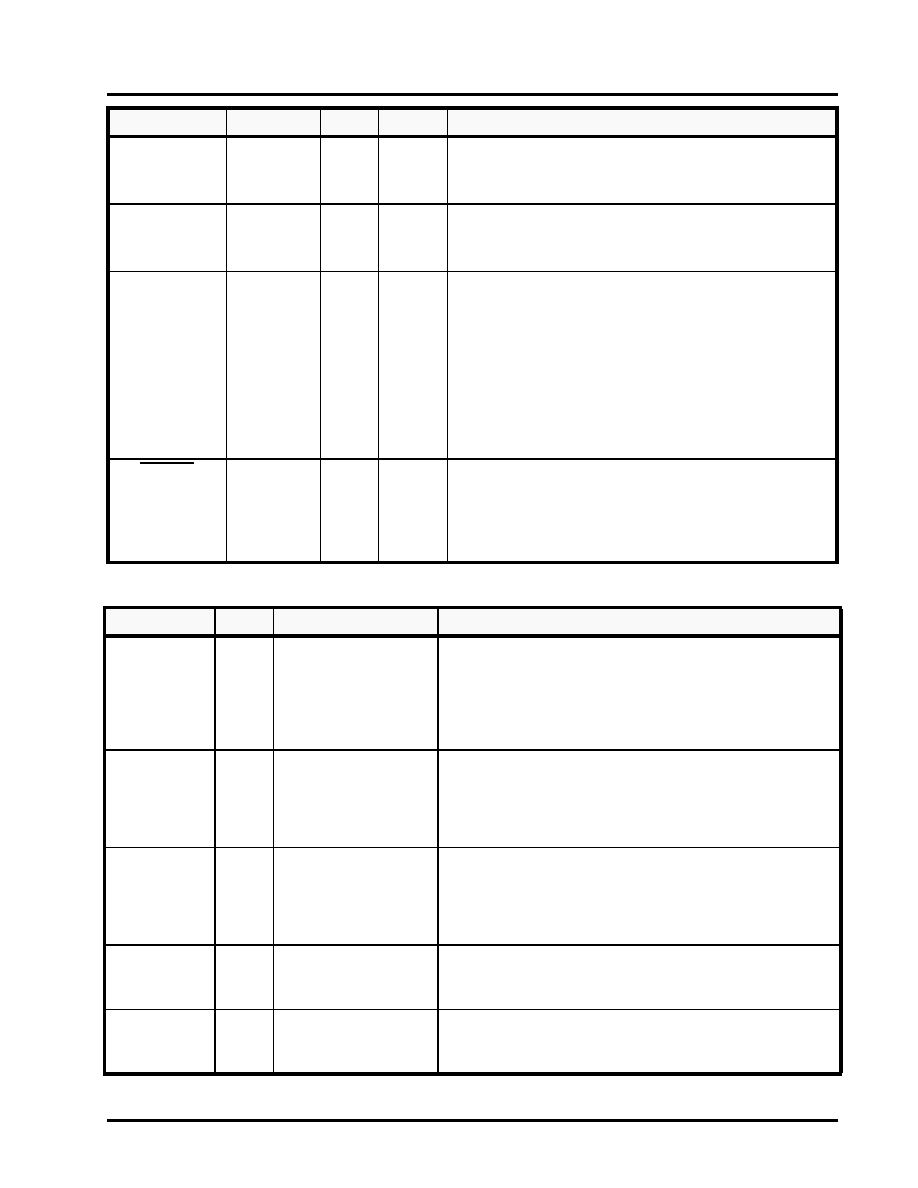
POWER AND GROUND
CAP1P
CAP2P
Analog
-
63
66
CDR Non-Inverting External Feeback Capacitor
C1 = 0.47
μF ± 10% tolerance
(Isolate from noise and place close to pin)
CAP1N
CAP2N
Analog
-
64
65
CDR Inverting External Feeback Capacitor
C2 = 0.47
μF ± 10% tolerance
(Isolate from noise and place close to pin)
DLOSDIS
LVTTL
I
17
LOS (Los of Signal) Detect Disable
Disables internal LOS monitoring and automatic muting of
RXDO[7:0] upon LOS detection (according to gating shown in
Figure 7.) LOS is declared when a string of 128 consecutive
zeros occur on the line. LOS condition is cleared when the 16
or more pulse transitions is detected for 128 bit period sliding
window.
"Low" = Monitor and Mute received data upon LOS declaration
"High" = Disable internal LOS monitoring (see Figure 7 for logic
operation.)
LOSEXT
SE-LVPECL
I
53
LOS or Signal Detect Input from Optical Module
Active "Low." When active, this pin can force the received data
output bus RXDO[7:0] to a logic state of ’0’ per Figure 7.
"Low" = Forced LOS
"High" = Normal Operation
NAME
TYPE
PIN
DESCRIPTION
VDD3.3
PWR
2,28,31,49,54,
58,76,99,81
3.3V CMOS Power Supply
VDD3.3 should be isolated from the analog VDD power supplies.
Use a ferrite bead along with an internal power plane separation.
The VDD3.3 power supply pins should have bypass capacitors to
the nearest ground. For best results, refer to Application notes
about general board layout guidelines.
AVDD3.3_TX
PWR
62
Analog 3.3V Transmitter Power Supply
AVDD3.3_TX should be isolated from the digital power supplies.
For best results, use a ferrite bead along with an internal power
plane separation. The AVDD3.3_TX power supply pins should
have bypass capacitors to the nearest ground.
AVDD3.3_RX
PWR
67,,68,69
Analog 3.3V Receiver Power Supply
AVDD3.3_RX should be isolated from the digital power supplies.
For best results, use a ferrite bead along with an internal power
plane separation. The AVDD3.3_RX power supply pins should
have bypass capacitors to the nearest ground.
VDD_LVPECL
PWR
9,15,21
3.3V Input/Output LVPECL Bus Power Supply
These pins require a 3.3V potential voltage for properly biasing
the Differential LVPECL input and output pins.
AGND_TX
PWR
59,60
Transmitter Analog Ground for 3.3V Analog Power Supplies
It is recommended that all ground pins of this device be tied
together.
NAME
LEVEL
TYPE
PIN
DESCRIPTION
相關(guān)PDF資料 |
PDF描述 |
|---|---|
| XRT91L30IQ-F | IC TXRX SONET/SDH 8BIT 64QFP |
| VI-BTF-MX-F1 | CONVERTER MOD DC/DC 72V 75W |
| XRT75VL00DIV-F | IC LIU E3/DS3/STS-1 1CH 52TQFP |
| VI-BTF-MW | CONVERTER MOD DC/DC 72V 100W |
| VI-BT4-MX-F3 | CONVERTER MOD DC/DC 48V 75W |
相關(guān)代理商/技術(shù)參數(shù) |
參數(shù)描述 |
|---|---|
| XRT91L32IQTR | 功能描述:LIN 收發(fā)器 PHY Transceiver RoHS:否 制造商:NXP Semiconductors 工作電源電壓: 電源電流: 最大工作溫度: 封裝 / 箱體:SO-8 |
| XRT91L32IQTR-F | 功能描述:LIN 收發(fā)器 PHY Transceiver RoHS:否 制造商:NXP Semiconductors 工作電源電壓: 電源電流: 最大工作溫度: 封裝 / 箱體:SO-8 |
| XRT91L33 | 制造商:EXAR 制造商全稱:EXAR 功能描述:STS-12/STS-3 MULTIRATE CLOCK AND DATA RECOVERY UNIT |
| XRT91L33AIG-F | 制造商:Exar Corporation 功能描述:CDR 155.52Mbps/622.08Mbps SONET/SDH 20-Pin TSSOP |
| XRT91L33ES | 功能描述:界面開發(fā)工具 Eval System for XRT91L33 Series RoHS:否 制造商:Bourns 產(chǎn)品:Evaluation Boards 類型:RS-485 工具用于評(píng)估:ADM3485E 接口類型:RS-485 工作電源電壓:3.3 V |
發(fā)布緊急采購(gòu),3分鐘左右您將得到回復(fù)。