- 您現(xiàn)在的位置:買賣IC網(wǎng) > PDF目錄16433 > XR16V598IQ-0B-EVB (Exar Corporation)EVAL BOARD FOR XR16V598-A 100QFP PDF資料下載
參數(shù)資料
| 型號: | XR16V598IQ-0B-EVB |
| 廠商: | Exar Corporation |
| 文件頁數(shù): | 32/58頁 |
| 文件大小: | 0K |
| 描述: | EVAL BOARD FOR XR16V598-A 100QFP |
| 標(biāo)準(zhǔn)包裝: | 1 |
| 系列: | * |
第1頁第2頁第3頁第4頁第5頁第6頁第7頁第8頁第9頁第10頁第11頁第12頁第13頁第14頁第15頁第16頁第17頁第18頁第19頁第20頁第21頁第22頁第23頁第24頁第25頁第26頁第27頁第28頁第29頁第30頁第31頁當(dāng)前第32頁第33頁第34頁第35頁第36頁第37頁第38頁第39頁第40頁第41頁第42頁第43頁第44頁第45頁第46頁第47頁第48頁第49頁第50頁第51頁第52頁第53頁第54頁第55頁第56頁第57頁第58頁
XR16V598
38
2.25V TO 3.6V HIGH PERFORMANCE OCTAL UART WITH 16-BYTE FIFO
REV. 1.0.3
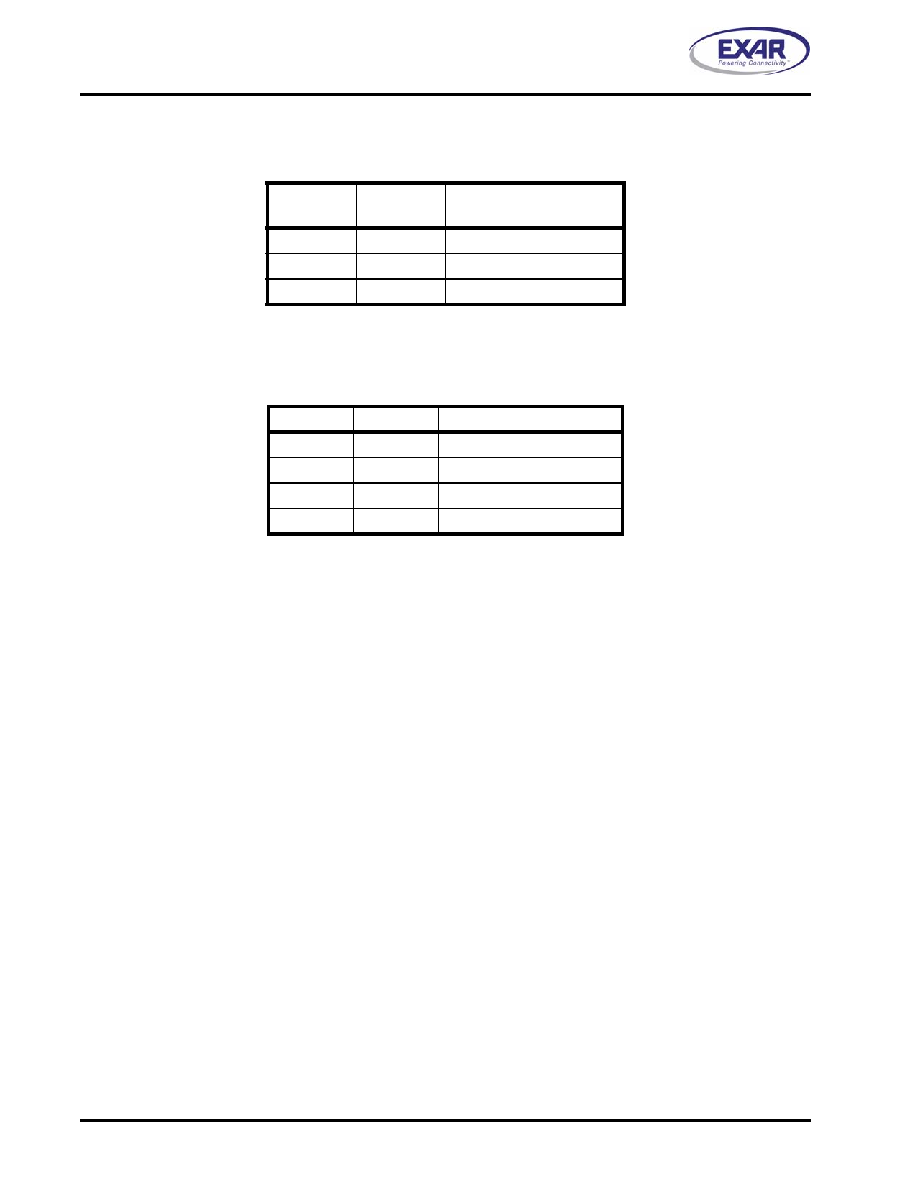
LCR[2]: TX and RX Stop-bit Length Select
The length of stop bit is specified by this bit in conjunction with the programmed word length.
LCR[1:0]: TX and RX Word Length Select
These two bits specify the word length to be transmitted or received.
4.7
Modem Control Register (MCR) - Read/Write
The MCR register is used for controlling the modem interface signals or general purpose inputs/outputs.
MCR[7]: Clock Prescaler Select
Logic 0 = Divide by one. The input clock from the crystal or external clock is fed directly to the Programmable
Baud Rate Generator without further modification, i.e., divide by one (default).
Logic 1 = Divide by four. The prescaler divides the input clock from the crystal or external clock by four and
feeds it to the Programmable Baud Rate Generator, hence, data rates become one forth.
MCR[6]: Infrared Encoder/Decoder Enable
The state of this bit depends on the sampled logic level of pin ENIR during power up, following a hardware
reset (rising edge of RST# input). Afterward user can override this bit for desired operation.
Logic 0 = Enable the standard modem receive and transmit character interface.
Logic 1 = Enable infrared IrDA receive and transmit inputs/outputs. While in this mode, the TX/RX output/
input are routed to the infrared encoder/decoder. The data input and output levels will conform to the IrDA
infrared interface requirement. As such, while in this mode the infrared TX output will be a logic 0 during idle
data conditions. FCTR bit-4 may be selected to invert the RX input signal level going to the decoder for
infrared modules that provide rather an inverted output.
MCR[5]: Xon-Any Enable
Logic 0 = Disable Xon-Any function (default).
Logic 1 = Enable Xon-Any function. In this mode any RX character received will enable Xon, resume data
transmission.
MCR[4]: Internal Loopback Enable
Logic 0 = Disable loopback mode (default).
Logic 1 = Enable local loopback mode, see loopback section and Figure 11.
BIT-2
WORD
LENGTH
STOP BIT LENGTH
(BIT TIME(S))
0
5,6,7,8
1 (default)
1
5
1-1/2
1
6,7,8
2
BIT-1
BIT-0
WORD LENGTH
0
5 (default)
0
1
6
1
0
7
1
8
相關(guān)PDF資料 |
PDF描述 |
|---|---|
| CM322522-820KL | INDUCTOR 82UH 60MA SMD |
| VI-2V2-EX | CONVERTER MOD DC/DC 15V 75W |
| XR16V598IQ-0A-EVB | EVAL BOARD FOR XR16V598-A 100QFP |
| APX809-46SRG-7 | IC MPU RESET CIRC 4.63V SOT23R-3 |
| 176819-000 | SOLDERSLEEVE LO-FIRE 11.5MM DIA |
相關(guān)代理商/技術(shù)參數(shù) |
參數(shù)描述 |
|---|---|
| XR16V598IQ100 | 制造商:EXAR 制造商全稱:EXAR 功能描述:2.25V TO 3.6V HIGH PERFORMANCE OCTAL UART WITH 16-BYTE FIFO |
| XR16V598IQ100-F | 功能描述:UART 接口集成電路 UART RoHS:否 制造商:Texas Instruments 通道數(shù)量:2 數(shù)據(jù)速率:3 Mbps 電源電壓-最大:3.6 V 電源電壓-最小:2.7 V 電源電流:20 mA 最大工作溫度:+ 85 C 最小工作溫度:- 40 C 封裝 / 箱體:LQFP-48 封裝:Reel |
| XR16V654 | 制造商:EXAR 制造商全稱:EXAR 功能描述:2.25V TO 3.6V QUAD UART WITH 64-BYTE FIFO |
| XR16V654_0709 | 制造商:EXAR 制造商全稱:EXAR 功能描述:2.25V TO 3.6V QUAD UART WITH 64-BYTE FIFO |
| XR16V654D | 制造商:EXAR 制造商全稱:EXAR 功能描述:2.25V TO 3.6V QUAD UART WITH 64-BYTE FIFO |
發(fā)布緊急采購,3分鐘左右您將得到回復(fù)。