- 您現(xiàn)在的位置:買賣IC網(wǎng) > PDF目錄372865 > XC9210B093KR (TOREX SEMICONDUCTOR LTD.) Synchronous Step-Down DC / DC Controller ICs PDF資料下載
參數(shù)資料
| 型號: | XC9210B093KR |
| 廠商: | TOREX SEMICONDUCTOR LTD. |
| 英文描述: | Synchronous Step-Down DC / DC Controller ICs |
| 中文描述: | 同步降壓DC / DC控制器芯片 |
| 文件頁數(shù): | 9/32頁 |
| 文件大小: | 425K |
| 代理商: | XC9210B093KR |
第1頁第2頁第3頁第4頁第5頁第6頁第7頁第8頁當(dāng)前第9頁第10頁第11頁第12頁第13頁第14頁第15頁第16頁第17頁第18頁第19頁第20頁第21頁第22頁第23頁第24頁第25頁第26頁第27頁第28頁第29頁第30頁第31頁第32頁
NOTES ON USE
1. Checking for Intermittent Oscillation
The XC9210 series is subject to intermittent oscillation in the proximity of the maximum duty if the step-down ratio is low (e.g., from 4.2 V to 3.3 V) or a
heavy load is applied where the duty ratio becomes high. Check waveforms at EXT under your operating conditions. A remedy for this problem is to
raise the inductance of coil L or increase the load capacitance CL and use OS-CON for the load capacitance CL. When using OS-CON for the load
capacitance and setting output voltage low, the series could produce an abnormal oscillation. In such case, please test with the actual device.
2. PWM/PFM Automatic Switching
If PWM/PFM automatic switching control is selected and the step-down ratio is high (e.g., from 10 V to 1.0 V), the control mode remains in PFM setting
over the whole load range, since the duty ratio under continuous-duty condition is smaller than the PFM duty ratio of the XC9210 series. The output
voltage's ripple voltage becomes substantially high under heavy load conditions, with the XC9210 series appearing to be producing an abnormal
oscillation. If this operation becomes a concern, set pins PWM1 and PWM2 to High to set the control mode to PWM setting. For use under the above-
mentioned condition, measured data of PWM/PFM automatic switching control shown on the data sheets are available up to IOUT = 100 mA.
3. Ratings
Use the XC9210 series and peripheral components within the limits of their ratings.
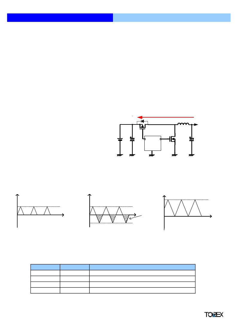
4. Reverse Current
Reverse current is produced under the
conditions of synchronous operation and light
load (current flows from the output to the input ).
If this reverse current becomes a concern,
operate under synchronous rectification during
heavy load conditions, or move input
capacitance CIN closer to the IC to reduce the
reverse current to the power supply.
5. Switching Method of Operational Mode / Control
9
* The light load condition mentioned above means that the load current when the coil current being discontinuous at non-synchronous operation. The heavy
load condition means that the load current when the coil current being continuous at non-synchronous operation. The DC/DC simulation on the TOREX
website is useful to determine whether the coil current is non-synchronous or synchronous under your operating conditions. After the simulation, please test
with the actual device.
Non-Synchronous, PFM / PWM Automatic Switching Control
OPERATIONAL MODE / CONTROL
Synchronous, PWM Control
Non-Synchronous, PWM Control
Non-Synchronous, PFM / PWM Automatic Switching Control
'L'
'H'
'L'
'H'
'L'
MODE
'H'
'H'
'L'
PWM
XC9210 Series
Synchronous Step-Down DC / DC Controller ICs
0mA
ILmax
Coil Current When Non-Synchronous
(Discontinuous Mode)
IL
0mA
ILmax
Reverse
Current
ILmin
Coil Current When Synchronous
ILmax
ILmin
IL
Coil Current with no reverse current
Comparison among non-synchronous operation (left), synchronous operation (center) and the coil current on a like-for-like
basis. Synchronous of the current IL< 0mA becomes reverse current.
To prevent the reverse current, operate in the condition of ILmin > 0mA (right).
Lx
EXT1
EXT2
IC
VOUT
CIN
VIN
GND
Reverse Current
L
CL
Semiconductor Ltd.
相關(guān)PDF資料 |
PDF描述 |
|---|---|
| XC9213 | Driver Transistor Built-In Synchronous Step-Down DC/DC Controller Ics |
| XC9213B103VRL | Driver Transistor Built-In Synchronous Step-Down DC/DC Controller Ics |
| XC9237C1BCER | 600mA Driver Tr. Built-In, Synchronous Step-Down DC/DC Converters |
| XC9237B3ACMR | 600mA Driver Tr. Built-In, Synchronous Step-Down DC/DC Converters |
| XC9237B3ADEL | 600mA Driver Tr. Built-In, Synchronous Step-Down DC/DC Converters |
相關(guān)代理商/技術(shù)參數(shù) |
參數(shù)描述 |
|---|---|
| XC9213 | 制造商:TOREX 制造商全稱:Torex Semiconductor 功能描述:Driver Transistor Built-In Synchronous Step-Down DC/DC Controller Ics |
| XC9213_1 | 制造商:TOREX 制造商全稱:Torex Semiconductor 功能描述:Synchronous Bootstrap N-ch & N-ch Driver |
| XC9213_2 | 制造商:TOREX 制造商全稱:Torex Semiconductor 功能描述:Synchronous Step-Down DC/DC Controller IC - Input Voltage : 25V |
| XC9213103VRL | 制造商:TOREX 制造商全稱:Torex Semiconductor 功能描述:Synchronous Step-Down DC/DC Controller IC - Input Voltage : 25V |
| XC9213B103VRL | 制造商:TOREX 制造商全稱:Torex Semiconductor 功能描述:Driver Transistor Built-In Synchronous Step-Down DC/DC Controller Ics |
發(fā)布緊急采購,3分鐘左右您將得到回復(fù)。