- 您現(xiàn)在的位置:買賣IC網(wǎng) > PDF目錄359455 > W172DIP-5 RELAY REED DIL 5VDC PDF資料下載
參數(shù)資料
| 型號: | W172DIP-5 |
| 英文描述: | RELAY REED DIL 5VDC |
| 中文描述: | 勵迪勒5Vdc時繼電器 |
| 文件頁數(shù): | 155/210頁 |
| 文件大小: | 7067K |
| 代理商: | W172DIP-5 |
第1頁第2頁第3頁第4頁第5頁第6頁第7頁第8頁第9頁第10頁第11頁第12頁第13頁第14頁第15頁第16頁第17頁第18頁第19頁第20頁第21頁第22頁第23頁第24頁第25頁第26頁第27頁第28頁第29頁第30頁第31頁第32頁第33頁第34頁第35頁第36頁第37頁第38頁第39頁第40頁第41頁第42頁第43頁第44頁第45頁第46頁第47頁第48頁第49頁第50頁第51頁第52頁第53頁第54頁第55頁第56頁第57頁第58頁第59頁第60頁第61頁第62頁第63頁第64頁第65頁第66頁第67頁第68頁第69頁第70頁第71頁第72頁第73頁第74頁第75頁第76頁第77頁第78頁第79頁第80頁第81頁第82頁第83頁第84頁第85頁第86頁第87頁第88頁第89頁第90頁第91頁第92頁第93頁第94頁第95頁第96頁第97頁第98頁第99頁第100頁第101頁第102頁第103頁第104頁第105頁第106頁第107頁第108頁第109頁第110頁第111頁第112頁第113頁第114頁第115頁第116頁第117頁第118頁第119頁第120頁第121頁第122頁第123頁第124頁第125頁第126頁第127頁第128頁第129頁第130頁第131頁第132頁第133頁第134頁第135頁第136頁第137頁第138頁第139頁第140頁第141頁第142頁第143頁第144頁第145頁第146頁第147頁第148頁第149頁第150頁第151頁第152頁第153頁第154頁當前第155頁第156頁第157頁第158頁第159頁第160頁第161頁第162頁第163頁第164頁第165頁第166頁第167頁第168頁第169頁第170頁第171頁第172頁第173頁第174頁第175頁第176頁第177頁第178頁第179頁第180頁第181頁第182頁第183頁第184頁第185頁第186頁第187頁第188頁第189頁第190頁第191頁第192頁第193頁第194頁第195頁第196頁第197頁第198頁第199頁第200頁第201頁第202頁第203頁第204頁第205頁第206頁第207頁第208頁第209頁第210頁
PART NUMBER SHOWN ALSO
AVAILABLE THRU STOCKING DISTRIBUTION
WEBSITE: www.magnecraft.com EMAIL:info@magnecraft.com FAX ON DEMAND 1-800/891-2957, DOCUMENT 100
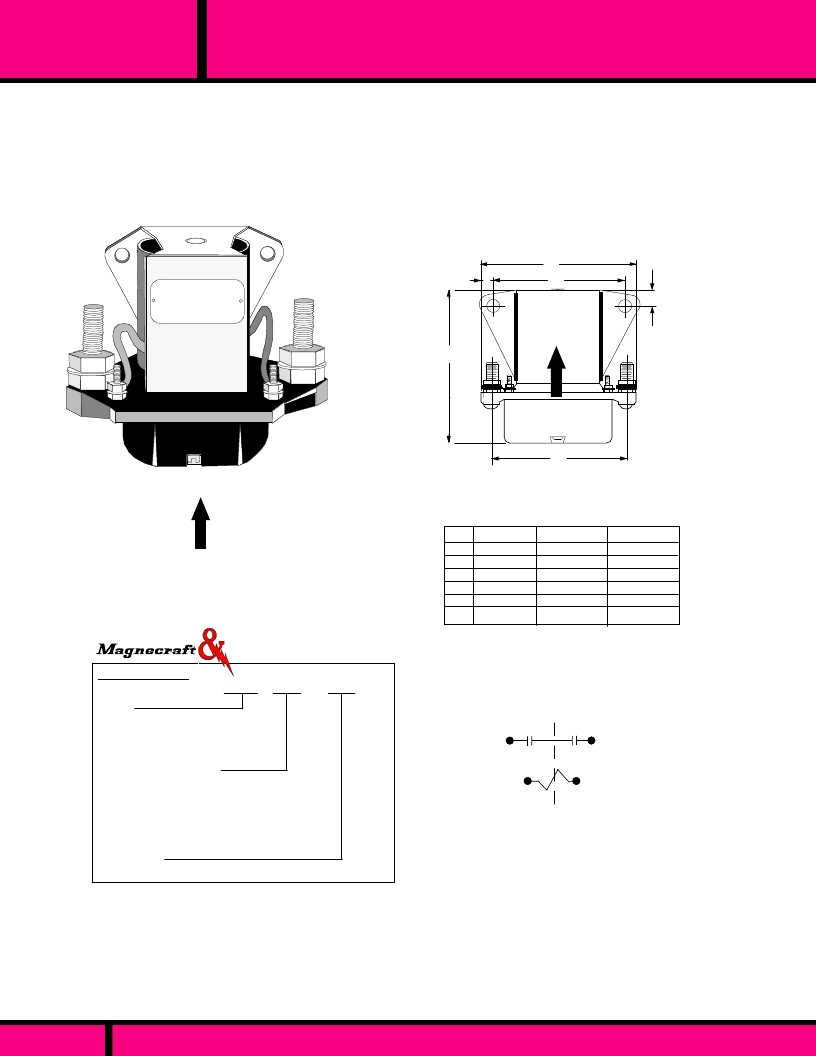
SERIES
101-102-103
50,100 & 200 AMP SINGLE POLE DC CONTACTORS
The Series 101, 102 and 103
are DC solenoid-actuated, heavy duty contactors.
Each contactor has a single pole, double-make normally open contact. Contacts
are enclosed with a molded plastic cover. The series 101 is rated at 50 amps
continuous duty. The series 102 is rated 100 amps continuous and the series 103 is
rated at 200 amps continuous. Coils are rated for DC only, as standard. The powerful
magnetic structure creates very high contact pressure which results in very reliable
and low resistance contacts, making them suitable for power applications in telecom-
munications, elevator and rail mass transit as well as other Industries.
ORDERING CODE
Typical Type No.
Series
101 Screw Term., 50 Amp, 1 pole
102 Screw Term., 100 Amp, 1 pole
103 Screw Term., 200 Amp, 1 pole
Contact Arrangements
HXX-
1 Pole D.M.- N.O. Standard.
HXH-
2 Pole D.B. -1 N.C. and 1 N.O.103 only.
JXX
- 2 Pole D.M. N.O
XRX
- SPDT-M-B (Make before break, 103 only)
XXH
- 1Pole-D.B. + 1NC
(103 only)
Coil Voltage
DC:
12, 28, 48, (Add
"D"
)
102 HXX -28D
Note: Contact arrangements other than the standard HXX will
require a 3 digit suffix number to be added to the type number.
This is done by the factory and will be shown after the contact
arrangement code. Contact factory for suffix number.
OPTIONS (CONSULT FACTORY)
AC COIL INPUT VOLTAGES
NON STANDARD DC COIL VOLTAGES
101HXX
102HXX
103HXX
WIRING DIAGRAM
A
B
C
D
E
F
2.69 (68.33)
1.87 (47.4)
2.50 (63.5)
1.84 (46.7)
0.40 (10.1)
0.43 (10.9)
3.38 (85.73)
2.25 (57.1)
3.22 (81.79)
2.09 (53.0)
0.56 (14.2)
0.50 (12.7)
4.25 (107.9)
2.40 (60.9)
3.53 (89.66)
2.65 (67.31)
0.92 (23.3)
0.56 (14.2)
101HXX
102HXX
103HXX
Mounting holes (2) - .265 (6.73) Inch Dia.
Dim.
Dimensions shown in Inch and (Millimeters)
Struthers-Dunn
A
B
D
E
F
(DEPTH FRONT TO BACK)
RECOMMENDED
MOUNTING POSITION
UP
OUTLINE DIMENSIONS
C
RECOMMENDED
MOUNTING POSITION
UP
PAGE 155
相關(guān)PDF資料 |
PDF描述 |
|---|---|
| W172DIP-150 | RELAY REED DIL 24VDC |
| W49RE1C2VF-6DC-SCO | SCHALTRELAIS SPCO |
| W49RE1C2VF-12DC-SCO | SCHALTRELAIS SPCO |
| W171DIP-9 | RELAY REED DIL 12VDC |
| W171DIP-7 | RELAY REED DIL 5VDC |
相關(guān)代理商/技術(shù)參數(shù) |
參數(shù)描述 |
|---|---|
| W172DIP-6 | 制造商:Magnecraft 功能描述: |
| W172DIP-7 | 功能描述:簧片繼電器 172DIP Mini Reed PCB Relay / SPDT, 0.25 A RoHS:否 制造商:MEDER electronic (Standex) 觸點形式:1 Form A (SPST-NO) 線圈電壓:5 VDC 最大開關(guān)功率:100 W 最大開關(guān)電流:1 A 線圈抑制二極管:No 線圈電阻:220 Ohms 端接類型: |
| W172DIP-8 | 功能描述:簧片繼電器 172DIP Mini Reed PCB Relay / SPDT, 0.25 A RoHS:否 制造商:MEDER electronic (Standex) 觸點形式:1 Form A (SPST-NO) 線圈電壓:5 VDC 最大開關(guān)功率:100 W 最大開關(guān)電流:1 A 線圈抑制二極管:No 線圈電阻:220 Ohms 端接類型: |
| W172E11 | 制造商:OMRON INDUSTRIAL AUTOMATION 功能描述:C200H VOICE OUTPUT MAN DX CODE ZA |
| W172SIP-4 | 制造商:Magnecraft 功能描述: |
發(fā)布緊急采購,3分鐘左右您將得到回復。