- 您現(xiàn)在的位置:買賣IC網(wǎng) > PDF目錄359455 > W171DIP25 FPGA 1.2K Gates 295 Cells 40MHz Military 1um (CMOS) Technology 5V 84-Pin CPGA PDF資料下載
參數(shù)資料
| 型號(hào): | W171DIP25 |
| 英文描述: | FPGA 1.2K Gates 295 Cells 40MHz Military 1um (CMOS) Technology 5V 84-Pin CPGA |
| 中文描述: | 勵(lì)迪勒5Vdc時(shí)繼電器 |
| 文件頁(yè)數(shù): | 113/210頁(yè) |
| 文件大?。?/td> | 7067K |
| 代理商: | W171DIP25 |
第1頁(yè)第2頁(yè)第3頁(yè)第4頁(yè)第5頁(yè)第6頁(yè)第7頁(yè)第8頁(yè)第9頁(yè)第10頁(yè)第11頁(yè)第12頁(yè)第13頁(yè)第14頁(yè)第15頁(yè)第16頁(yè)第17頁(yè)第18頁(yè)第19頁(yè)第20頁(yè)第21頁(yè)第22頁(yè)第23頁(yè)第24頁(yè)第25頁(yè)第26頁(yè)第27頁(yè)第28頁(yè)第29頁(yè)第30頁(yè)第31頁(yè)第32頁(yè)第33頁(yè)第34頁(yè)第35頁(yè)第36頁(yè)第37頁(yè)第38頁(yè)第39頁(yè)第40頁(yè)第41頁(yè)第42頁(yè)第43頁(yè)第44頁(yè)第45頁(yè)第46頁(yè)第47頁(yè)第48頁(yè)第49頁(yè)第50頁(yè)第51頁(yè)第52頁(yè)第53頁(yè)第54頁(yè)第55頁(yè)第56頁(yè)第57頁(yè)第58頁(yè)第59頁(yè)第60頁(yè)第61頁(yè)第62頁(yè)第63頁(yè)第64頁(yè)第65頁(yè)第66頁(yè)第67頁(yè)第68頁(yè)第69頁(yè)第70頁(yè)第71頁(yè)第72頁(yè)第73頁(yè)第74頁(yè)第75頁(yè)第76頁(yè)第77頁(yè)第78頁(yè)第79頁(yè)第80頁(yè)第81頁(yè)第82頁(yè)第83頁(yè)第84頁(yè)第85頁(yè)第86頁(yè)第87頁(yè)第88頁(yè)第89頁(yè)第90頁(yè)第91頁(yè)第92頁(yè)第93頁(yè)第94頁(yè)第95頁(yè)第96頁(yè)第97頁(yè)第98頁(yè)第99頁(yè)第100頁(yè)第101頁(yè)第102頁(yè)第103頁(yè)第104頁(yè)第105頁(yè)第106頁(yè)第107頁(yè)第108頁(yè)第109頁(yè)第110頁(yè)第111頁(yè)第112頁(yè)當(dāng)前第113頁(yè)第114頁(yè)第115頁(yè)第116頁(yè)第117頁(yè)第118頁(yè)第119頁(yè)第120頁(yè)第121頁(yè)第122頁(yè)第123頁(yè)第124頁(yè)第125頁(yè)第126頁(yè)第127頁(yè)第128頁(yè)第129頁(yè)第130頁(yè)第131頁(yè)第132頁(yè)第133頁(yè)第134頁(yè)第135頁(yè)第136頁(yè)第137頁(yè)第138頁(yè)第139頁(yè)第140頁(yè)第141頁(yè)第142頁(yè)第143頁(yè)第144頁(yè)第145頁(yè)第146頁(yè)第147頁(yè)第148頁(yè)第149頁(yè)第150頁(yè)第151頁(yè)第152頁(yè)第153頁(yè)第154頁(yè)第155頁(yè)第156頁(yè)第157頁(yè)第158頁(yè)第159頁(yè)第160頁(yè)第161頁(yè)第162頁(yè)第163頁(yè)第164頁(yè)第165頁(yè)第166頁(yè)第167頁(yè)第168頁(yè)第169頁(yè)第170頁(yè)第171頁(yè)第172頁(yè)第173頁(yè)第174頁(yè)第175頁(yè)第176頁(yè)第177頁(yè)第178頁(yè)第179頁(yè)第180頁(yè)第181頁(yè)第182頁(yè)第183頁(yè)第184頁(yè)第185頁(yè)第186頁(yè)第187頁(yè)第188頁(yè)第189頁(yè)第190頁(yè)第191頁(yè)第192頁(yè)第193頁(yè)第194頁(yè)第195頁(yè)第196頁(yè)第197頁(yè)第198頁(yè)第199頁(yè)第200頁(yè)第201頁(yè)第202頁(yè)第203頁(yè)第204頁(yè)第205頁(yè)第206頁(yè)第207頁(yè)第208頁(yè)第209頁(yè)第210頁(yè)
PAGE 113
WEBSITE: www.magnecraft.com EMAIL:info@magnecraft.com FAX ON DEMAND 1-800/891-2957, DOCUMENT 100
WHAT A TIME DELAY RELAY IS:
A Time Delay relay is a combination of an electromechanical output
relay and a control circuit. The control circuit is comprised of solid state
components and timing circuits that control operation of the relay and
timing range. Typical time delay functions include On-Delay, Off-Delay,
Repeat cycle, One Shot, Batch Control Interval, On-Delay & Off Delay
(Combination) and True Off Delay. Each function is explained below.
Time delay relays have a broad choice of timing ranges from less than
one second to hours. There is a choice of timing controls from calibrated
external knob, screwdriver adjusted or internally fixed timing for specific
applications. The output contacts on the electromechanical output relay
are direct wired to the output terminals. The contact load ratings are
specified for each specific type of time delay relay.
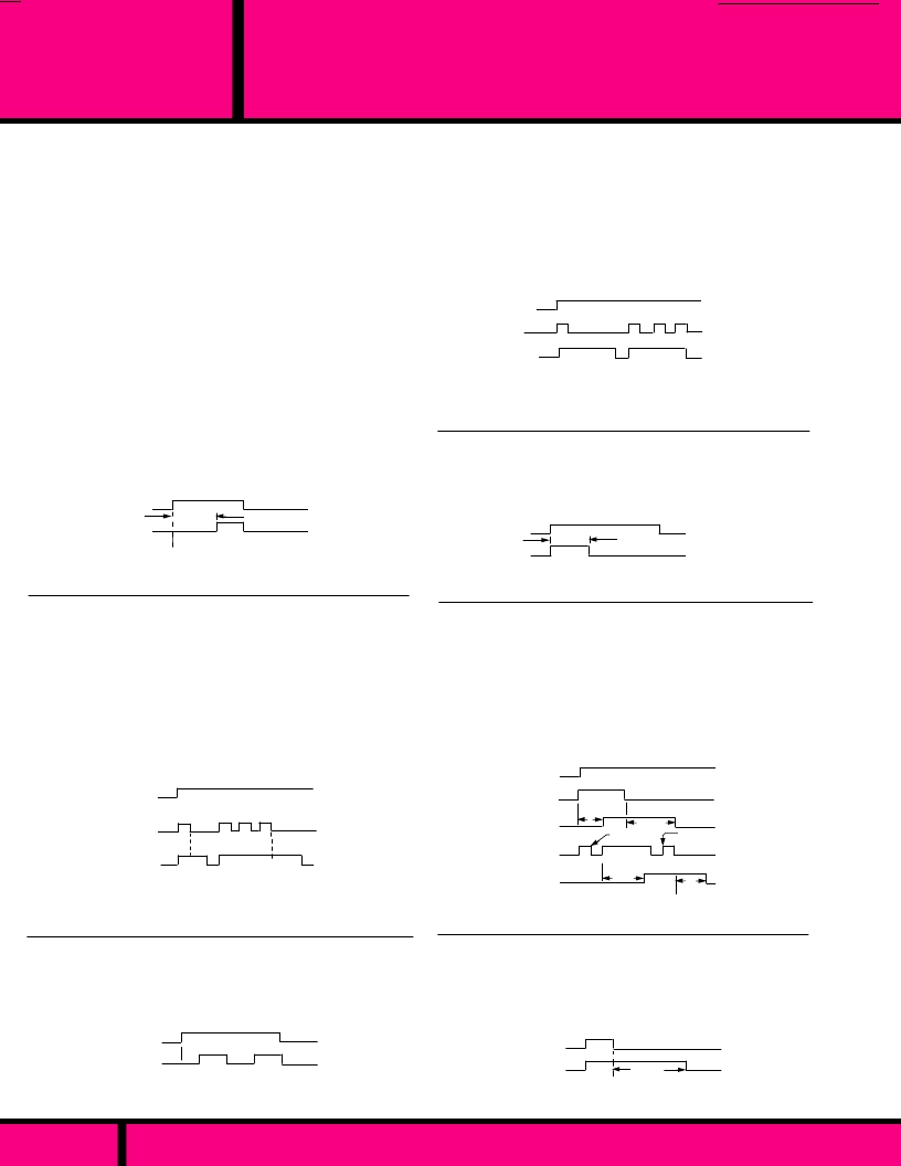
TIMING FUNCTIONS:
Some typical Applications:
Signs, Product testing, signal devices,
machine control, Signal warning devices, conveyor control.
OFF
TRANSFERRED
ON
OFF DELAY
ON DELAY
ON DELAY
INPUT
POWER
OUTPUT
CONTACTS
REPEAT CYCLE (FLASHER) -
Upon application of power to the input,
the Off time delay Period begins. The contacts transfer at the end of the
Off time Delay Period and the ON time delay period begins. At the end
of the ON time delay period output contacts return home and OFF time
delay period begins again. This sequence will continue as long as input
power is supplied to the Input Pins.
Some typical Applications:
Air Conditioning, automatic Door Controls,
Lighting Controls, burglar alarms, Vending Machines, conveyor
systems, instrument control.
DELAY
HOME
OFF
TRANSFERRED
ON
INPUT
POWER
OUTPUT
CONTACTS
Some typical Applications:
Cascade starting, Air Conditioning & heating
controls, Burglar Alarms, Power Outage delay, instrument Control.
OFF-DELAY (SLOW RELEASE RELAY)
Continuous power must be applied to input during all timing sequences.
Upon closure of external control switch, output contacts transfer. Upon
opening control switch, the timing period begins. When timing period
ends, output contacts return home. To repeat this timing cycle, the
control switch must be re-closed and then opened. If input power is
interrupted during timing cycle, the output contacts return to home
position and the control switch must be closed and reopened to start the
timing from the beginning. If the control switch closes during a timing
period, timing stops and output contacts remain transferred. When control
switch is opened, timing will start again from the beginning. The timing
period can be extended, repeatedly using the control switch in this way
until the last initiated timing period is permitted to end and output contacts
return home.
HOME
Some typical Applications:
Loss of power alarm control, Burglar
alarms.
DELAY
OFF DELAY
INPUT
POWER
OUTPUT
CONTACTS
HOME
TRUE OFF DELAY- (SLOW RELEASE)
Upon application of power to the input, output contacts transfer. The
delay period begins when power is removed from the input. If power
is supplied to input during the timing period, time is reset and time
delay period starts over again when power is removed from the input.
Some typical Applications:
Cascade starting & stopping of heavy
loads, laboratory equipment, machine control
T
2
T
1
T
2
T
1
T
1
Interrupted
T
2
Interrupted
OPEN
CONTROL SWITCH
INPUT
POWER
OPEN
TRANSFERRED
OFF
CLOSED
CLOSED
ON
HOME
TRANSFERRED
ON-DELAY & OFF-DELAY- (COMBINATION)
Continuous power must be applied to the input during all timing
sequences. Upon closure of the external control switch, first time delay
period T
begins. When T
period ends, output contacts transfer.
Then, When control switch is opened, second delay period T
begins.
When T
ends, output contacts return home. To repeat this timing
cycle, repeat this sequence from the beginning. If the prevailing open
or closed status of the control switch is changed during either T
or T
2
Timing periods, timing stops. Position of output contacts remain as they
were. Returning control switch to its pre-changed position restarts
interrupted timing period from the beginning and normal timing resumes.
Some typical Applications:
Machine control, End of process alarm,
Welding control, Photographic timing.
OFF
TRANSFERRED
ON
INPUT
POWER
DELAY
HOME
BATCH CONTROL (INTERVAL)
Upon application of power to the input, the output contacts transfer
and the delay period begins. At the end of the time delay period, the
output contacts return home. Input power must be interrupted to
recycle timer.
TRANSFERRED
OFF
TIMING FUNCTIONS (Continued)
ONE SHOT (MOMENTARY ACTUATION)
Continuous power must be applied to the input during all timing
sequences. Upon closure of external control Switch, output contacts
transfer and timing period begins. When timing period ends, output
contacts return home. Once the timing period begins, the control
switch may remain closed or opened without affecting timing. To
repeat this cycle, the control switch must be open, or opened at the
end of the timing period, and then closed to start timing period over
again.
DESCRIPTIONS
OF TIME DELAY
FUNCTIONS
APPLICATION DATA
ON-DELAY- (SLOW OPERATE RELAY)
Upon application of power to
the input, the time delay period begins. At the end of the time delay
period, output contacts transfer. Input power must be removed to return
output contacts to home position and reset the control circuit. If input
power is interrupted before a timing period ends, timing stops. When
input power is restored , timing starts from the beginning.
Special requirements for Class 211 programmable relays: To function as
an On-Delay timer, as described above, a jumper wire must be connected
in place of the external control switch.
OUTPUT
CONTACTS
OUTPUT
CONTACTS
OUTPUT
CONTACTS
CONTROL
SWITCH
HOME
TRANSFERRED
OUTPUT
CONTACTS
ON
OFF
INPUT
POWER
DELAY
DELAY
INPUT
POWER
CONTROL
SWITCH
DELAY
Some typical Applications:
Vending machines, dispensing controls,
machine control, welding control,
CONTROL SWITCH
HOME
DELAY
OFF
CLOSED
ON
HOME
TRANSFERRED
OPEN
OPEN
CLOSED
OUTPUT
CONTACTS
相關(guān)PDF資料 |
PDF描述 |
|---|---|
| W1C1801 | Assemblies |
| W1C1803 | Assemblies |
| W1C1K1 | Assemblies |
| W1C1K2 | Assemblies |
| W1C1K3 | Assemblies |
相關(guān)代理商/技術(shù)參數(shù) |
參數(shù)描述 |
|---|---|
| W171DIP-25 | 功能描述:簧片繼電器 171DIP Mini Reed PCB Relay / DPST, 0.5 A RoHS:否 制造商:MEDER electronic (Standex) 觸點(diǎn)形式:1 Form A (SPST-NO) 線圈電壓:5 VDC 最大開(kāi)關(guān)功率:100 W 最大開(kāi)關(guān)電流:1 A 線圈抑制二極管:No 線圈電阻:220 Ohms 端接類型: |
| W171DIP-25 | 制造商:Magnecraft 功能描述:RELAY REED DPST-NO 5V 制造商:Magnecraft 功能描述:REED RELAY 制造商:Magnecraft 功能描述:RELAY, REED, DPST-NO, 5V |
| W171DIP-26 | 制造商:Magnecraft 功能描述: |
| W171DIP27 | 制造商:Magnecraft 功能描述:3-5 Days |
| W171DIP-27 | 功能描述:簧片繼電器 171DIP Mini Reed PCB Relay / DPST, 0.5 A RoHS:否 制造商:MEDER electronic (Standex) 觸點(diǎn)形式:1 Form A (SPST-NO) 線圈電壓:5 VDC 最大開(kāi)關(guān)功率:100 W 最大開(kāi)關(guān)電流:1 A 線圈抑制二極管:No 線圈電阻:220 Ohms 端接類型: |
發(fā)布緊急采購(gòu),3分鐘左右您將得到回復(fù)。