- 您現(xiàn)在的位置:買賣IC網(wǎng) > PDF目錄297787 > VXS150-3 FREQUENZUMRICHTER 3 PHASEN 1.5KW PDF資料下載
參數(shù)資料
| 型號(hào): | VXS150-3 |
| 英文描述: | FREQUENZUMRICHTER 3 PHASEN 1.5KW |
| 中文描述: | FREQUENZUMRICHTER 3 PHASEN 1.5千瓦 |
| 文件頁(yè)數(shù): | 2/4頁(yè) |
| 文件大?。?/td> | 108K |
| 代理商: | VXS150-3 |
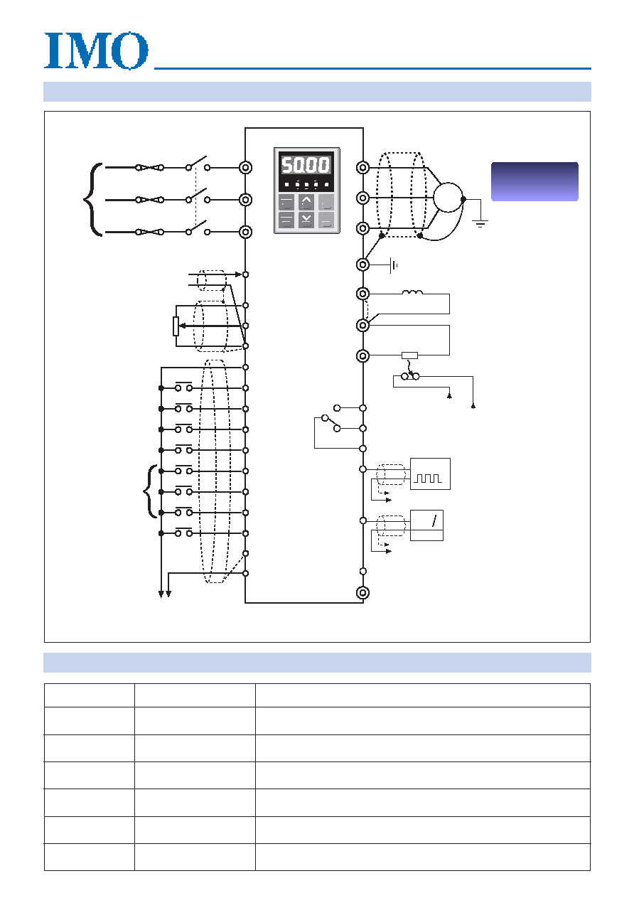
Connection diagram
Jaguar VXS
F
C
L1
FL2
(L)
FL3
(N)
C 1
1 3
1 2
1 1
P24
FWD
REV
BX
RST
X1
X2
X3
X4
CM
THR
U
V
W
M
GND(PE)
P 1
(+)
D B
30A
30B
30C
FMP
FMA
YIE
CMC
(+)
(–)
PULSE
LINK
EXTERNAL
BRAKE RESISTOR (OPTIONAL)
DC REACTOR (OPTIONAL)
Power Terminals
Symbol
Terminal Name
Description
L1, L2, L3
For connecting 3 phase power supply (VXS - 3 only)
L, N
For connecting single phase power supply (VXS - 1 only)
U, V, W
For 3 phase AC induction motor
P1, (+)
(+), DB
Connection for brake resistor to increase braking torque
GND (PE)
Earth terminal
Safety electrical earth
Main input
power terminals
Main input
power terminals
Power output
terminals
DC reactor
terminals
External brake
resistor terminals
Optional DC reactor terminals for improving
power factor (fitted with shorting link)
NOTE: Under no circumstances should the above guide be considered sufficient for the attainment of relevant EMC emission
limits. Please consult the product manual for full information regarding compliance.
Common for YIE
Programmable output
To terminal 11
WARNING! This equipment must be earthed
CAUTION: Do not short circuit. Terminal
P24 to terminal 11, CM or CME
Digital
frequency
meter
To CM terminal
Analog
frequency
meter
(10 V/1 mA DC)
*
From P24
terminal
From THR
terminal
Alarm output (any fault)
(Relay shown in power ON or OFF and healthy state)
NOTE: Figures in brackets are for
single phase models
Frequency reference
current input
(4~20 mA DC)
Manual frequency
setting potentiometer
(10K
/1W)
+24V
Forward operation
and stop command
Reverse operation
and stop command
Coast - to - stop
command
Alarm reset
Multistep
frequency select
Function
extension input
External alarm
input
240V
1
or
415V
3
50/60 Hz
*
GND(PE)
PANEL
CONTROL
PRG MODE
RUN
Hz
A
V
r/min
m/min
PRG
RESET
RUN
FUNC
DATA
STOP
PRICE
INFORMATION
AND ORDERING
PRICE
INFORMATION
AND ORDERING
相關(guān)PDF資料 |
PDF描述 |
|---|---|
| VXS20-1 | VX75KP DRIVE ((NS)) |
| VXS220-1 | FREQUENZUMRICHTER 1 PHASE 2.2KW |
| VXS220-3 | FREQUENZUMRICHTER 3 PHASEN 2.2KW |
| VXS400-3 | FREQUENZUMRICHTER 3 PHASEN 4.0KW |
| VXS40-1 | FREQUENZUMRICHTER 1 PHASE 0.4KW |
相關(guān)代理商/技術(shù)參數(shù) |
參數(shù)描述 |
|---|---|
| VXS1925 | 制造商:CPI 制造商全稱:CPI 功能描述:Crossed-Field Amplifier |
| VXS20-1 | 制造商:未知廠家 制造商全稱:未知廠家 功能描述:VX75KP DRIVE ((NS)) |
| VXS220-1 | 制造商:未知廠家 制造商全稱:未知廠家 功能描述:FREQUENZUMRICHTER 1 PHASE 2.2KW |
| VXS220-3 | 制造商:未知廠家 制造商全稱:未知廠家 功能描述:FREQUENZUMRICHTER 3 PHASEN 2.2KW |
| VXS2230S-03F-BTR1 | 制造商:SMC 功能描述:2 Port Solenoid Valve,G3/8,24Vdc |
發(fā)布緊急采購(gòu),3分鐘左右您將得到回復(fù)。