- 您現(xiàn)在的位置:買賣IC網 > PDF目錄297769 > VKA50LS15-1 (CD TECHNOLOGIES INC) 1-OUTPUT 50 W DC-DC REG PWR SUPPLY MODULE PDF資料下載
參數(shù)資料
| 型號: | VKA50LS15-1 |
| 廠商: | CD TECHNOLOGIES INC |
| 元件分類: | 電源模塊 |
| 英文描述: | 1-OUTPUT 50 W DC-DC REG PWR SUPPLY MODULE |
| 文件頁數(shù): | 4/4頁 |
| 文件大?。?/td> | 743K |
| 代理商: | VKA50LS15-1 |
4
VKA50xS Rev D 2/2004
Product: www.cdpoweronline.com
1.000
[25.40]
1.400
[35.56]
2.000
[50.80]
0.19 [4.8]
0.20 [5.1]
0.50 [12.7]
0.40 [10.16]
0.530 MAX
[13.46]
0.20 [5.1]
.040 [1.02] DIA.
7 PLACES
.081 [2.06] DIA.
2 PLACES
1.400
[35.56]
1.000
[25.40]
0.700
[17.78]
.400 [10.16]
1.900
[48.26]
2.28
[57.91]
MAX
MOUNTING INSERTS M3 X 0.5 THRU, 4 PLACES
MAX.TORQUE, 8 IN/LBS
2.40
[61.0]
MAX
Power Electronics Division, Americas
3400 E Britannia Drive, Tucson, Arizona 85706
Tel: 800.547.2537 Fax: 520.770.9369
C&D Technologies, (NCL). EMEA/AP
Milton Keynes MK14 5BU UK
Tel: +44 (0)1908 615232 Fax: +44 (0)1908 617545
MECHANICAL
Any data, prices, descriptions or specications presented herein are subject to revision by C&D Technologies, Inc. without notice. While such information is believed to be
accurate as indicated herein, C&D Technologies, Inc. makes no warranty and hereby disclaims all warranties, express or implied, with regard to the accuracy or complete-
ness of such information. Further, because the product(s) featured herein may be used under conditions beyond its control, C&D Technologies, Inc. hereby disclaims all
warranties, either express or implied, concerning the tness or suitability of such product(s) for any particular use or in any specic application or arising from any course of
dealing or usage of trade. The user is solely responsible for determining the suitability of the product(s) featured herein for user’s intended purpose and in user’s specic
application. C&D Technologies, Inc. does not warrant or recommend that any of its products be used in any life support or aviation or aerospace applications.
Special attention should be given to the peak voltage
deviation during a dynamic load step when trimming
the output above the original set point to avoid
tripping the overvoltage protection circuit. Should an
OVP condition occur, the converter will go into a latch
condition and must be externally reset before it will
return to normal operation.
This feature allows the user to accurately adjust the mod-
ule’s output voltage set point to a specied level. This is
achieved by connecting a resistor or potentiometer from
the TRIM terminal to either the +Vout terminal (for increased
Vout) or the -Vout terminal (for decreased Vout). The formu-
lae below describe the trim resistor value to obtain a Vout
change of
D%. VO is output voltage prior to adjustment
(3.3V, 5V, 12V, 15V, or 24V).
Radj - up =
(
Vo(100 +
D%) _ (100 + 2D%) ) kW
1.225
D%
Radj - down =
(100 - 2) kW
D%
NOTES:
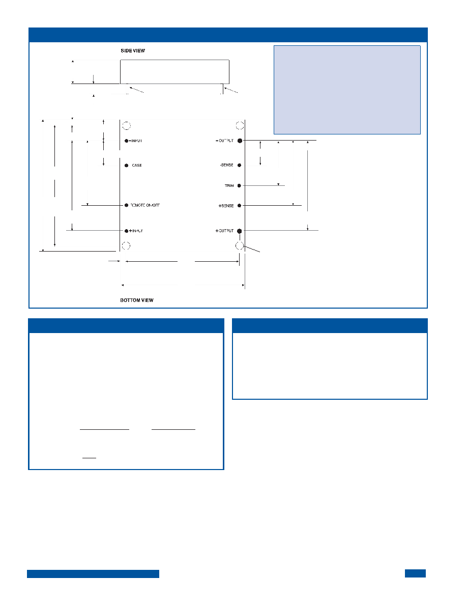
All dimensions are in inches (millimeters).
PIN PLACEMENT TOLERANCE: ± 0.005”
MECHANICAL TOLERANCE: ± 0.015”
Marked with: specic modeL ordered, date code, job
code.
MATERIAL:Unitsareencapsulatedinalowthermalresistance
molding compound which has excellent chemical resistance
and electrical properties in high humidity environments and
over a wide operating temperature range. The encapsulant
andoutershelloftheunithaveUL94V-0ratings.Leadmaterial
is solder plated to allow ease of solderability.
OUTPUT ADJUST VOLTAGE
OVP NOTE
VKA50xS
相關PDF資料 |
PDF描述 |
|---|---|
| VKA50LS15-61 | 1-OUTPUT 50 W DC-DC REG PWR SUPPLY MODULE |
| VKA50LS24-81 | 1-OUTPUT 50 W DC-DC REG PWR SUPPLY MODULE |
| VKA50MS05-6 | 1-OUTPUT 50 W DC-DC REG PWR SUPPLY MODULE |
| VKA50LS05-61 | 1-OUTPUT 50 W DC-DC REG PWR SUPPLY MODULE |
| VKA50LS05-8 | 1-OUTPUT 50 W DC-DC REG PWR SUPPLY MODULE |
相關代理商/技術參數(shù) |
參數(shù)描述 |
|---|---|
| VKA50LS15-1C | 功能描述:DC/DC轉換器 VKA50LS15-1C RoHS:否 制造商:Murata 產品: 輸出功率: 輸入電壓范圍:3.6 V to 5.5 V 輸入電壓(標稱): 輸出端數(shù)量:1 輸出電壓(通道 1):3.3 V 輸出電流(通道 1):600 mA 輸出電壓(通道 2): 輸出電流(通道 2): 安裝風格:SMD/SMT 封裝 / 箱體尺寸: |
| VKA50LS15-6 | 制造商:未知廠家 制造商全稱:未知廠家 功能描述:Analog IC |
| VKA50LS15-61 | 制造商:未知廠家 制造商全稱:未知廠家 功能描述:Analog IC |
| VKA50LS15-8 | 制造商:未知廠家 制造商全稱:未知廠家 功能描述:Analog IC |
| VKA50LS15-81 | 制造商:未知廠家 制造商全稱:未知廠家 功能描述:Analog IC |
發(fā)布緊急采購,3分鐘左右您將得到回復。