- 您現(xiàn)在的位置:買賣IC網(wǎng) > PDF目錄297729 > VI-AWW-MU SPECIALTY ANALOG CIRCUIT, DMA9 PDF資料下載
參數(shù)資料
| 型號(hào): | VI-AWW-MU |
| 元件分類: | 模擬信號(hào)調(diào)理 |
| 英文描述: | SPECIALTY ANALOG CIRCUIT, DMA9 |
| 封裝: | rohs compliant, package-9 |
| 文件頁數(shù): | 3/5頁 |
| 文件大?。?/td> | 213K |
| 代理商: | VI-AWW-MU |
Vicor Corp. Tel: 800-735-6200, 978-470-2900 Fax: 978-475-6715
VI-IAM Input Attenuator Modules
Rev. 1.2
Page 3 of 5
Set your site on VICOR at www.vicorpower.com
VI-IAM
Gate Out
Parallel
Gate In
+Out
-Out
-In
+In
+
–
+In
Gate In
Gate Out
-In
VI-200/J00
C1
4700 pF
F1
F2
10V
U2
U1
OC
OV
Vref
2
Vref 1
+OUT
–OUT
Level
Shift
–IN
+IN
–IN
+IN
GATE IN
GATE OUT
PARALLEL
Q1
Q2
EMI Filter
D1
D2
C2
0.1
1
10ms
100
1000
100V
Normal Operating Area
I.S.W.
Full Load
100V
Standard
Wide Range
24 V Inputs
0.1
1
10ms
100
1000
800V
Normal Operating Area
I.S.W.
Full Load
300 V Input
S.D.
160V
0.1
1
10ms
100
1000
Normal Operating Area
I.S.W.
Full Load
48 V Input
R.E.
276V
Normal Operating Area
I.S.W.
Full Load
0.1
1
10ms
100
1000
48 V Wide Range Input
R.E.
S.D.
R.E.
32V
21V
36V
18V
S.D.
76V
125V
60V
100V
42V
500V
400V
200V
36V
S.D.
100V
500ms
I.S.W.: Input surge withstand (no disruption of performance)
R.E.: Ratings exceeded
S.D.: Shut down
Figure 1 — Safe operating area based on input voltage of IAM
(1% duty cycle max., Zs=0.5
Ω, for short duration transient
capability refer to specifications.)
24 V
20 A / 32 V (AGC-20)
24 V “W”
20 A / 36 V (AGC-20)
48 V
20 A / 60 V (3AB-20)
48 V “N”
20 A / 80 V (3AB-20)
300 V
5 A / 250 V Bussman PC-Tron
Table 1 — Recommended F1 fusing based on input voltage (see Fig3)
Input Voltage
Recommended Fuse
24 Vdc (21 – 32 V)
470 F
24 Vdc (18 – 36 V)
470 F
48 Vdc (42 – 60 V)
220 F
48 Vdc (36 – 76 V)
120 F
300 Vdc (200 – 400 V)
27 F
[a]
Capacitance should be distributed across the input of each
DC-DC converter. (C1, Figure 3)
Table 2 — Recommended distributed capacitance on input of DC-
DC converter(s)
Input Voltage
Maximum Capacitance[a]
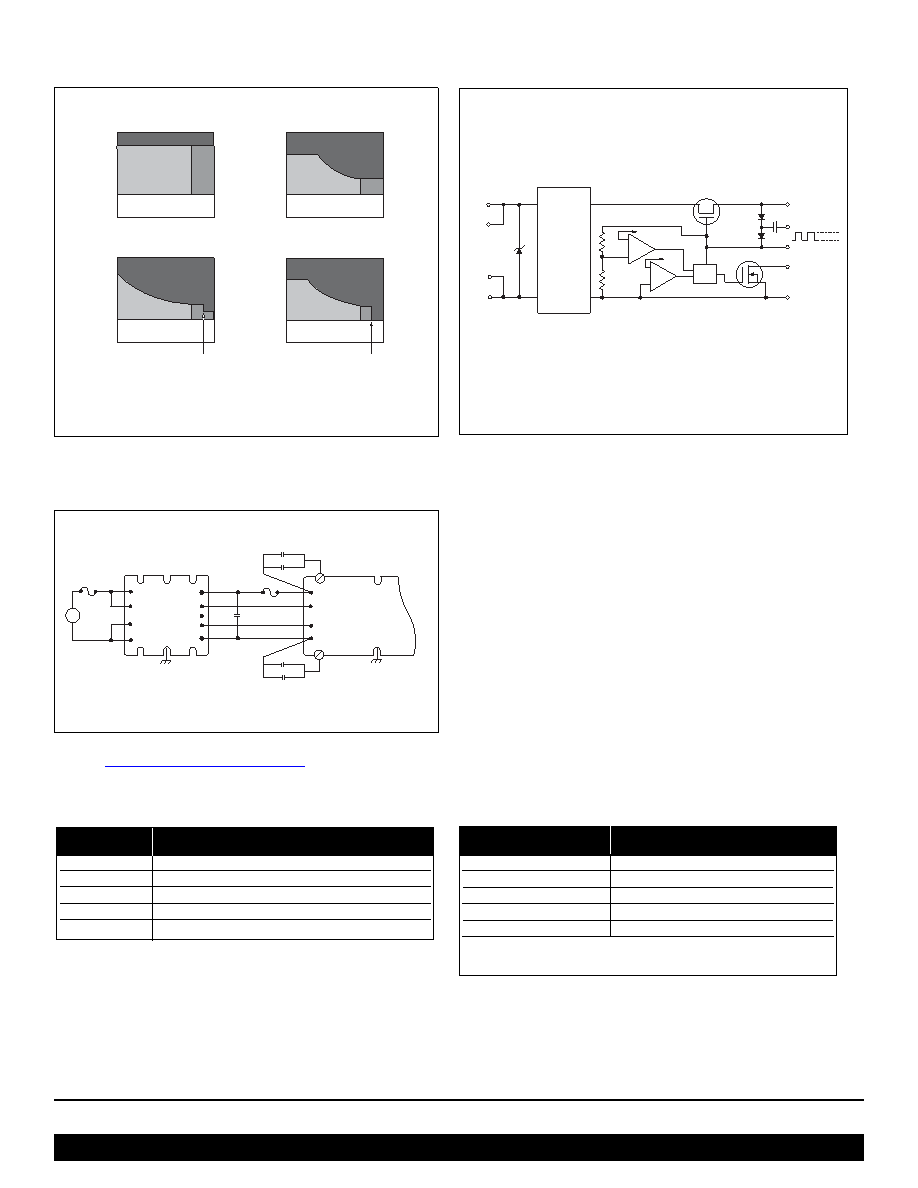
Figure 2 — Block diagram of Input Attenuator Module (IAM)
Figure 3 — Typical connection diagram. For recommended fuse
(F2) see VI-200 / VI-J00 application manual.
相關(guān)PDF資料 |
PDF描述 |
|---|---|
| VE-A66-IQ | SPECIALTY ANALOG CIRCUIT, DMA9 |
| VE-AWW-IU | SPECIALTY ANALOG CIRCUIT, DMA9 |
| VE-A66-CQ | SPECIALTY ANALOG CIRCUIT, DMA9 |
| VI-A11-IU | SPECIALTY ANALOG CIRCUIT, DMA9 |
| VE13P00251KED | |
相關(guān)代理商/技術(shù)參數(shù) |
參數(shù)描述 |
|---|---|
| VIB0001TFJ | 制造商:VICOR 制造商全稱:Vicor Corporation 功能描述:BCM Bus Converter |
| VIB0002TFJ | 制造商:VICOR 制造商全稱:Vicor Corporation 功能描述:HV Bus Converter Family |
| VIB0003TFJ | 制造商:VICOR 制造商全稱:Vicor Corporation 功能描述:DC to DC Bus Converter Module |
| VIB0010TFJ | 制造商:VICOR 制造商全稱:Vicor Corporation 功能描述:DC to DC Bus Converter Module |
| VI-B00-CW | 制造商:POWERBOX 制造商全稱:Powerbox 功能描述:50 - 200W PCB MOUNTING COMPONENETS |
發(fā)布緊急采購(gòu),3分鐘左右您將得到回復(fù)。