- 您現(xiàn)在的位置:買賣IC網(wǎng) > PDF目錄384047 > UPG503B (NEC Corp.) 9 GHz DIVIDE-BY-4 DYNAMIC PRESCALER PDF資料下載
參數(shù)資料
| 型號: | UPG503B |
| 廠商: | NEC Corp. |
| 英文描述: | 9 GHz DIVIDE-BY-4 DYNAMIC PRESCALER |
| 中文描述: | 9 GHz的分頻4動態(tài)預(yù)分頻器 |
| 文件頁數(shù): | 3/4頁 |
| 文件大?。?/td> | 57K |
| 代理商: | UPG503B |

*
V
SS1
should be connected to GND through a 2.2 V Zener Diode
(RD2.2FB or IN3394).
V
DD
= 3.8 V
V
SS1
= 0 V (GND)
V
SS2
= –2.2 V
C: 1000 - 5000 pF Chip Capacitor
V
DD
= +6.0 V
V
SS2
= 0 V (GND)
C: 1000 - 5000 pF Chip Capacitor
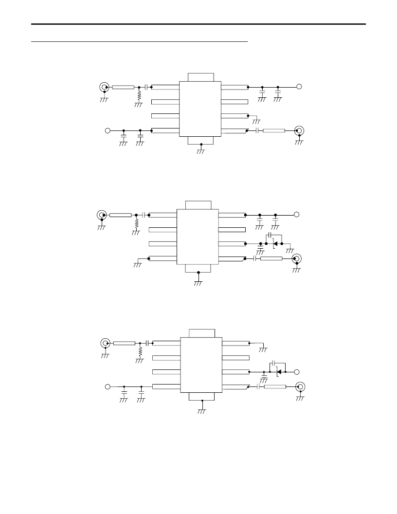
CONFIGURATION 2
Single Positive Bias Supply
CONFIGURATION 3
Single Negative Bias Supply
V
DD
= 0 V (GND)
V
SS2
= –6 V
C: 1000 - 5000 pF Chip Capacitor
CONFIGURATION 1
2 Bias Supply
*
For V
SS1,
the bias voltage of -6.0 should be applied through a 2.2 V
Zener Diode (RD2.2FB or IN3394).
POWER SUPPLY CONFIGURATIONS
(V
GG1
and V
GG2
are normally open)
Notes:
1. Because of the high internal gain and gain compression of the UPG503B, the device is prone to self-oscillation in the absence of an RF input
signal. This self-oscillation can be suppressed by either of the following means:
Add a shunt resistor to the RF input line. Typically a resistor value between 50 and 1000 ohms will suppress the self-
oscillation (see the test circuit schematic).
Apply a negative voltage through a 1000 ohm resistor to the normally open V
GG1
connection. Typically voltages between
0 and -9 volts will suppress the self-oscillation.
Both of these approaches will reduce the input sensitivity of the device (by as much as 3 dB for a 50 ohm shunt resistor), but otherwise have no
effect on the reliability or electrical characteristics of the device.
C
See Note 1
OPEN
OPEN
OPEN
IN
Zo = 50
10
μ
F
C
10
μ
F
V
SS2
(-6 V)
OUT
Zo = 50
5 IN
6 V
GG1
7 V
GG2
8 V
SS2
V
DD
4
NC 3
V
SS1
2
OUT 1
2.2 V
C
C
-6 V*
C
See Note 1
OPEN
OPEN
OPEN
IN
Zo = 50
GND (0 V) V
SS2
10
μ
F
*
C
10
μ
F
V
DD
(+6 V)
OUT
Zo = 50
5 IN
7 V
GG2
8 V
SS2
V
DD
4
NC 3
V
SS1
2
OUT 1
2.2 V
C
C
6 V
GG1
C
See Note 1
OPEN
OPEN
OPEN
IN
Zo = 50
V
SS2
(-2.2 V)
10
μ
F
C
C
10
μ
F
V
DD
(3.8 V)
V
SS1
(0 V) GND
OUT
Zo = 50
5 IN
6 V
GG1
7 V
GG2
8 V
SS2
V
DD
4
NC 3
V
SS1
2
OUT 1
C
相關(guān)PDF資料 |
PDF描述 |
|---|---|
| US1A-13-F | 1.0A SURFACE MOUNT ULTRA-FAST RECTIFIER |
| US1M-13-F | 1.0A SURFACE MOUNT ULTRA-FAST RECTIFIER |
| US3C | 3.0A SURFACE MOUNT SUPER-FAST RECTIFIER |
| US3F | 3.0A SURFACE MOUNT SUPER-FAST RECTIFIER |
| US5L12 | General purpose transistor (isolated transistor and diode) |
相關(guān)代理商/技術(shù)參數(shù) |
參數(shù)描述 |
|---|---|
| UPG503P | 制造商:未知廠家 制造商全稱:未知廠家 功能描述:Analog IC |
| UPG504B | 制造商:未知廠家 制造商全稱:未知廠家 功能描述:Analog IC |
| UPG504P | 制造商:未知廠家 制造商全稱:未知廠家 功能描述:Analog IC |
| UPG506B | 制造商:NEC 制造商全稱:NEC 功能描述:14 GHz DIVIDE-BY-8 DYNAMIC PRESCALER |
| UPG506P | 制造商:未知廠家 制造商全稱:未知廠家 功能描述:Analog IC |
發(fā)布緊急采購,3分鐘左右您將得到回復(fù)。