- 您現(xiàn)在的位置:買賣IC網(wǎng) > PDF目錄382718 > UC2633QTR Iso high side smart power solid state relay PDF資料下載
參數(shù)資料
| 型號(hào): | UC2633QTR |
| 英文描述: | Iso high side smart power solid state relay |
| 中文描述: | 模擬鎖相環(huán) |
| 文件頁(yè)數(shù): | 2/8頁(yè) |
| 文件大?。?/td> | 588K |
| 代理商: | UC2633QTR |

PARAMETER
TEST CONDITIONS
MIN.
TYP.
20
MAX. UNITS
28
Supply Current
Reference
Output Voltage (V
REF
)
Load Regulation
Line Regulation
Short Circuit Current
Oscillator
DC Voltage Gain
Input DC Level (V
IB
)
Input Impedance (Note 3)
Output DC Level
Maximum Operating Frequency
Dividers
Maximum Input Frequency
Div. 4/5 Input Current
+V
IN
= 15V
mA
4.75
5.0
5.0
2.0
30
5.25
20
20
V
I
OUT
= 0V to 7mA
+V
IN
= 8V to 15V
V
OUT
= 0V
mV
mV
mA
12
Oscillator Input to Oscillator Output
Oscillator Input Pin Open, T
J
= 25°C
V
IN
= V
IB
±
0.5V, T
J
= 25
°
C
Oscillator Input Pin Open, T
J
= 25°C
12
1.15
1.3
1.2
10
16
1.3
1.6
1.4
20
1.45
1.9
1.6
dB
V
k
V
MHz
Input = 1V
PP
at Oscillator Input
Input = 5V (Div. by 4)
Input = 0V (Div. by 5)
10
MHz
μ
A
μ
A
V
150
0.0
1.6
500
5.0
2.2
-5.0
0.5
Div. 4/5 Threshold
Note 3: These impedence levels will vary with T
J
at about 1700ppm/°C
UC1633
UC2633
UC3633
Input Supply Voltage (+V
IN
) . . . . . . . . . . . . . . . . . . . . . . . . +20V
Reference Output Current . . . . . . . . . . . . . . . . . . . . . . . . -30mA
Op-Amp Output Currents . . . . . . . . . . . . . . . . . . . . . . . .
±
30mA
Op-Amp Input Voltages . . . . . . . . . . . . . . . . . . . . . -.3V to +20V
Phase Detector Output Current . . . . . . . . . . . . . . . . . . .
±
10mA
Lock Indicator Output Current . . . . . . . . . . . . . . . . . . . . +15mA
Lock Indicator Output Voltage . . . . . . . . . . . . . . . . . . . . . . +20V
Divide Select Input Voltages . . . . . . . . . . . . . . . . . -.3V to +10V
Double Edge Disable Input Voltage . . . . . . . . . . . . -.3V to +10V
Oscillator Input Voltage . . . . . . . . . . . . . . . . . . . . . . -.3V to +5V
Sense Amplifier Input Voltage . . . . . . . . . . . . . . . . .3V to +20V
Power Dissipation at T
A
= 25°C (Note 2 . . . . . . . . . . . 1000mW
Power dissipation at T
C
= 25°C (Note 2) . . . . . . . . . . . 2000mW
Operating Junction Temperature . . . . . . . . . . . -55°C to +150°C
Storage Temperature . . . . . . . . . . . . . . . . . . . . -65°C to +150°C
Lead Temperature (Soldering, 10 Seconds) . . . . . . . . . . 300°C
ABSOLUTE MAXIMUM RATINGS
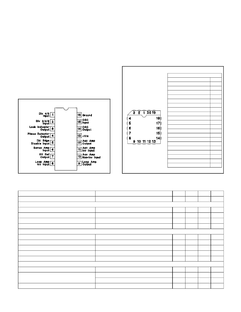
CONNECTION DIAGRAMS
PACKAGE PIN FUNCTION
FUNCTION
N/C
Div 4/5 Input
Div 2/4/8 Input
Lock Indicator Output
Phase Detector Output
N/C
Dbl Edge Disable Input
Sense Amp Input
5V Ref Output
Loop Amp Inv Input
N/C
Loop Amp Output
Aux Amp Non-Inv Input
Aux Amp Inv Input
Aux Amp Output
N/C
+V
IN
OSC Output
OSC Input
Ground
PIN
1
2
3
4
5
6
7
8
9
10
11
12
13
14
15
16
17
18
19
20
PLCC-20 (TOP VIEW)
Q Package
Note1: Voltages are referenced to ground, (Pin 16). Currents
are positive into, negative out of, the specified terminals.
Note 2: Consult Packaging Section of Databook for thermal limi-
tations and considerations of package.
DIL-16 (TOP VIEW)
J or N Package
ELECTRICAL CHARACTERISTICS:
(Unless otherwise stated, these specifications apply for T
A
= 0°C to +70°C for the
UC3633, -25
°
C to +85
°
C for the UC2633, -55°C to +125°C for the UC1633, +V
IN
=
12V; T
A
=T
J
.)
2
Powered by ICminer.com Electronic-Library Service CopyRight 2003
相關(guān)PDF資料 |
PDF描述 |
|---|---|
| UC3633J | DMOS driver for bipolar stepper motor |
| UC3633Q | Analog Phase-Locked Loop |
| UC3633QTR | Stepper motor driver |
| UC2727J | Single channel high side driver |
| UC1727J | 8-bit MCU for automotive with Flash or ROM, 10-bit ADC, 5 timers, SPI, LINSCI", active CAN |
相關(guān)代理商/技術(shù)參數(shù) |
參數(shù)描述 |
|---|---|
| UC2634 | 制造商:TI 制造商全稱:Texas Instruments 功能描述:Phase Locked Frequency Controller |
| UC2634 WAF | 制造商:Texas Instruments 功能描述: |
| UC2634DW | 制造商:未知廠家 制造商全稱:未知廠家 功能描述:Analog Phase-Locked Loop |
| UC2634DWTR | 制造商:未知廠家 制造商全稱:未知廠家 功能描述:Analog Phase-Locked Loop |
| UC2634J | 制造商:未知廠家 制造商全稱:未知廠家 功能描述:Analog Phase-Locked Loop |
發(fā)布緊急采購(gòu),3分鐘左右您將得到回復(fù)。