- 您現(xiàn)在的位置:買賣IC網(wǎng) > PDF目錄98307 > TVP7002PZPR (TEXAS INSTRUMENTS INC) SPECIALTY CONSUMER CIRCUIT, PQFP100 PDF資料下載
參數(shù)資料
| 型號(hào): | TVP7002PZPR |
| 廠商: | TEXAS INSTRUMENTS INC |
| 元件分類: | 消費(fèi)家電 |
| 英文描述: | SPECIALTY CONSUMER CIRCUIT, PQFP100 |
| 封裝: | GREEN, PLASTIC, HTQFP-100 |
| 文件頁(yè)數(shù): | 3/57頁(yè) |
| 文件大小: | 517K |
| 代理商: | TVP7002PZPR |
第1頁(yè)第2頁(yè)當(dāng)前第3頁(yè)第4頁(yè)第5頁(yè)第6頁(yè)第7頁(yè)第8頁(yè)第9頁(yè)第10頁(yè)第11頁(yè)第12頁(yè)第13頁(yè)第14頁(yè)第15頁(yè)第16頁(yè)第17頁(yè)第18頁(yè)第19頁(yè)第20頁(yè)第21頁(yè)第22頁(yè)第23頁(yè)第24頁(yè)第25頁(yè)第26頁(yè)第27頁(yè)第28頁(yè)第29頁(yè)第30頁(yè)第31頁(yè)第32頁(yè)第33頁(yè)第34頁(yè)第35頁(yè)第36頁(yè)第37頁(yè)第38頁(yè)第39頁(yè)第40頁(yè)第41頁(yè)第42頁(yè)第43頁(yè)第44頁(yè)第45頁(yè)第46頁(yè)第47頁(yè)第48頁(yè)第49頁(yè)第50頁(yè)第51頁(yè)第52頁(yè)第53頁(yè)第54頁(yè)第55頁(yè)第56頁(yè)第57頁(yè)

SLES206B
– MAY 2007 – REVISED MAY 2011
FUNCTIONAL DESCRIPTION
Analog Channel
The TVP7002 contains three identical analog channels that are independently programmable. Each channel
consists of a clamping circuit, programmable gain control, programmable offset control, and an ADC.
Analog Input Switch Control
TVP7002 has three analog channels that accept up to ten video inputs. The user can configure the internal
analog video switches via the I2C interface. The ten analog video inputs can be used for different input
configurations, some of which are:
Up to three SDTV, EDTV, or HDTV component video inputs (limited by number of SOG inputs)
Up to two 5-wire PC graphics inputs (limited by number of HSYNC and VSYNC inputs)
The input selection is performed by the input select register at I2C subaddress 19h a 1Ah (see Input
Mux Select 1 and Input Mux Select 2).
Supported Video Formats
The TVP7002 supports A/D conversion of SDTV (480i, 576i), EDTV (480p, 576p), and HDTV (720p, 1080i,
1080p) YPbPr component video inputs. The TVP7002 also supports A/D conversion and color space conversion
of all standard PC graphics formats (RGB) from VGA up to UXGA. The internal sync separator provides support
for field rates (VSYNC frequencies) at or above 40 Hz. Separated VSYNC or an external sync separator must be
used to support formats having field rates less than 40 Hz. A summary of the analog video standards supported
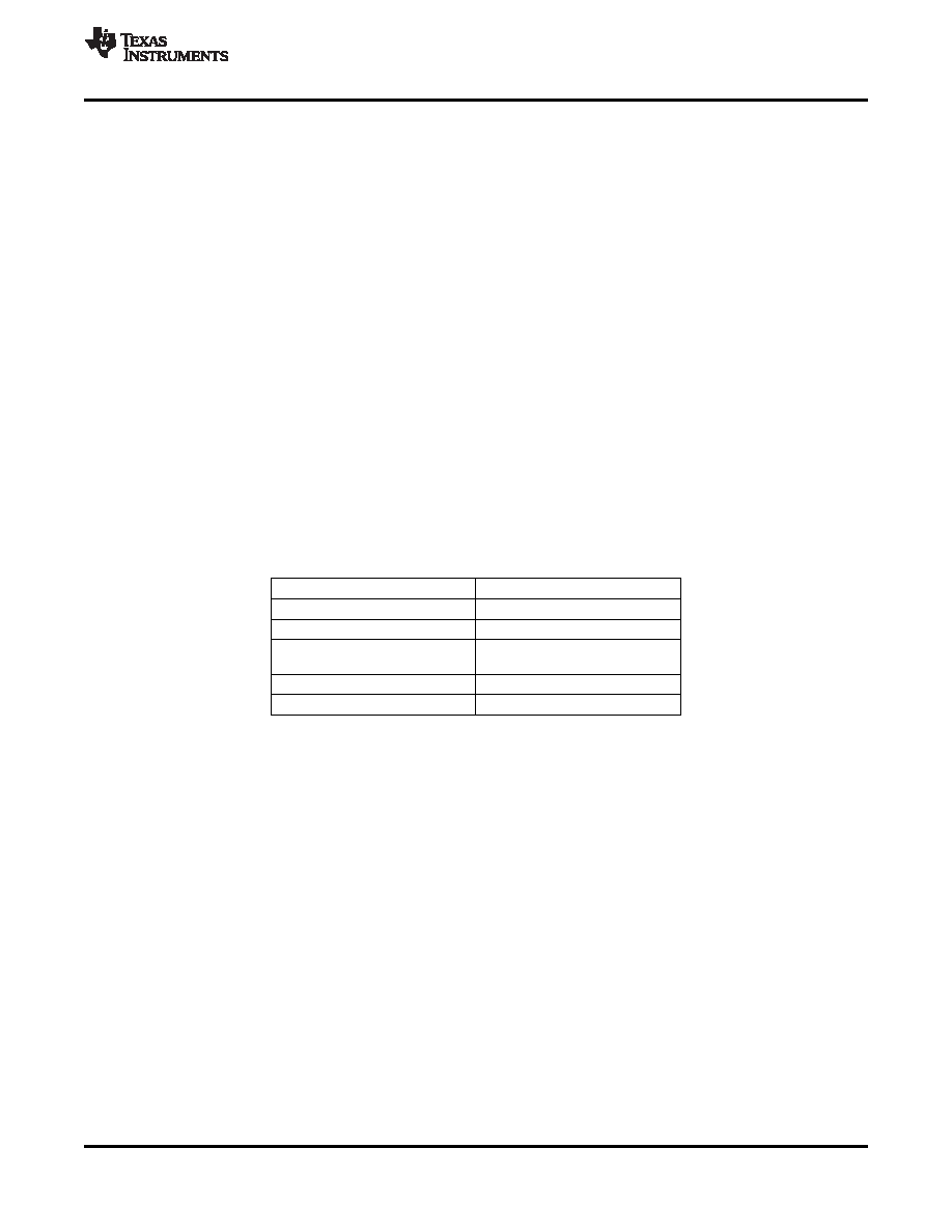
by the TVP7002 module is show in Table 2.
Table 2. Analog Video Standards
VIDEO FORMAT
VIDEO STANDARDS
SDTV (YPbPr component)
480i, 576i
EDTV (YPbPr component)
480p, 576p
720p50, 720p60, 1080i50,
HDTV (YPbPr component)
1080i60, 1080p50, 1080p60
PC graphics (RGB component)
VGA to UXGA
SCART (RGB component)
576i
Analog Input Clamping
The TVP7002 provides dc restoration for all analog video inputs including the SOG slicer inputs. The dc
restoration circuit (a.k.a. clamp circuit) restores the ac-coupled video signal to a fixed dc level. One dc restoration
circuit is implemented prior to each of the three ADCs, and a fourth one is located prior to the SOG slicer. The dc
restoration circuit can be programmed to operate as either a sync-tip clamp (a.k.a. coarse clamp) or a
back-porch clamp (a.k.a. fine clamp). The sync-tip clamp always clamps the video sync-tip level near the bottom
of the ADC range. The back-porch type clamp supports two clamping levels (bottom level and mid level) that are
selectable using bits 0, 1, and 2 of register 10h. When using the fine bottom-level clamp, an optional 300-mV
common-mode offset may be selected using bit 7 of register 2Ah.
In general, the analog video input being used for horizontal synchronization purposes should always use the
sync-tip clamp; all other analog video inputs should use the back-porch clamp. The advantage of the back-porch
clamp is that it has negligible video droop or tilt across a video line.
Copyright
2007–2011, Texas Instruments Incorporated
11
相關(guān)PDF資料 |
PDF描述 |
|---|---|
| TVP7002PZP | SPECIALTY CONSUMER CIRCUIT, PQFP100 |
| TWL1101PFB | SPECIALTY CONSUMER CIRCUIT, PQFP48 |
| TWL1101PFBR | SPECIALTY CONSUMER CIRCUIT, PQFP48 |
| TWL1102PBS | SPECIALTY CONSUMER CIRCUIT, PQFP32 |
| TWL1102PBSR | SPECIALTY CONSUMER CIRCUIT, PQFP32 |
相關(guān)代理商/技術(shù)參數(shù) |
參數(shù)描述 |
|---|---|
| TVP9000MZDSR | 制造商:Texas Instruments 功能描述: |
| TVP9000ZDS | 制造商:Texas Instruments 功能描述: |
| TVP9000ZDSR | 制造商:Texas Instruments 功能描述: |
| TVP9001ZDS | 制造商:Texas Instruments 功能描述: |
| TVP9001ZDSR | 制造商:Texas Instruments 功能描述: |
發(fā)布緊急采購(gòu),3分鐘左右您將得到回復(fù)。