- 您現在的位置:買賣IC網 > PDF目錄98283 > TPS57040QDGQRQ1 (TEXAS INSTRUMENTS INC) SWITCHING REGULATOR, 2500 kHz SWITCHING FREQ-MAX, PDSO10 PDF資料下載
參數資料
| 型號: | TPS57040QDGQRQ1 |
| 廠商: | TEXAS INSTRUMENTS INC |
| 元件分類: | 穩(wěn)壓器 |
| 英文描述: | SWITCHING REGULATOR, 2500 kHz SWITCHING FREQ-MAX, PDSO10 |
| 封裝: | GREEN, PLASTIC, MSOP-10 |
| 文件頁數: | 25/51頁 |
| 文件大?。?/td> | 1871K |
| 代理商: | TPS57040QDGQRQ1 |
第1頁第2頁第3頁第4頁第5頁第6頁第7頁第8頁第9頁第10頁第11頁第12頁第13頁第14頁第15頁第16頁第17頁第18頁第19頁第20頁第21頁第22頁第23頁第24頁當前第25頁第26頁第27頁第28頁第29頁第30頁第31頁第32頁第33頁第34頁第35頁第36頁第37頁第38頁第39頁第40頁第41頁第42頁第43頁第44頁第45頁第46頁第47頁第48頁第49頁第50頁第51頁
IND
Vinmax
Vout
Io
K
Vinmax
sw
-
(
)
=
f
OUT
RIPPLE
O
SW
V
Vin m ax
- V
I
Vin m ax
L
( )
(
)
2
OUT
L(rms)
O
SW
V
Vinmax
- V
1
I
12
Vinmax
L
=
+
÷
÷
è
f
2
Iripple
Iout
ILpeak
+
=
SLVSAP4A
– DECEMBER 2010 – REVISED APRIL 2011
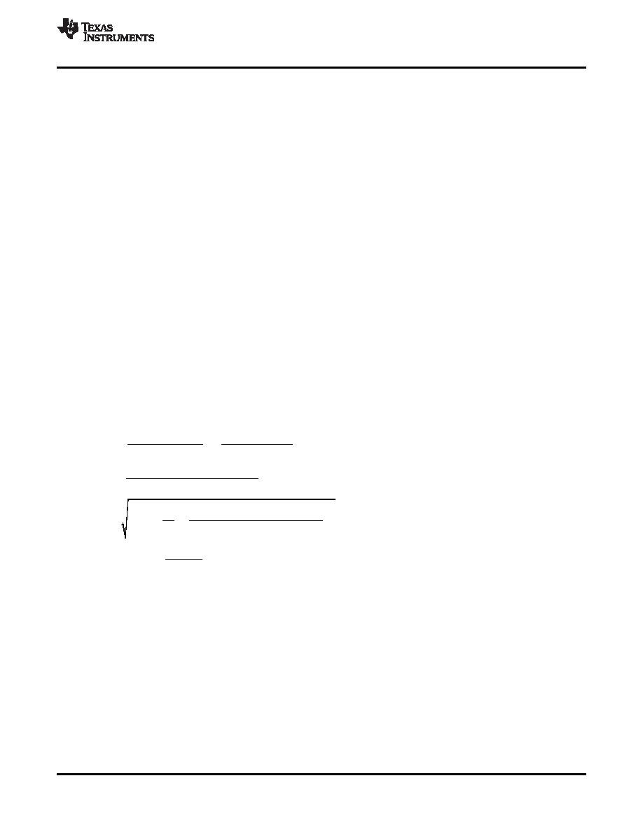
Output Inductor Selection (LO)
To calculate the minimum value of the output inductor, use Equation 28.
KIND is a coefficient that represents the amount of inductor ripple current relative to the maximum output current.
The inductor ripple current will be filtered by the output capacitor. Therefore, choosing high inductor ripple
currents will impact the selection of the output capacitor since the output capacitor must have a ripple current
rating equal to or greater than the inductor ripple current. In general, the inductor ripple value is at the discretion
of the designer; however, the following guidelines may be used.
For designs using low ESR output capacitors such as ceramics, a value as high as KIND = 0.3 may be used.
When using higher ESR output capacitors, KIND = 0.2 yields better results. Since the inductor ripple current is
part of the PWM control system, the inductor ripple current should always be greater than 30 mA for dependable
operation. In a wide input voltage regulator, it is best to choose an inductor ripple current on the larger side. This
allows the inductor to still have a measurable ripple current with the input voltage at its minimum.
For this design example, use KIND = 0.3 and the minimum inductor value is calculated to be 42 μH. For this
design, a nearest standard value was chosen: 47
μH. For the output filter inductor, it is important that the RMS
current and saturation current ratings not be exceeded. The RMS and peak inductor current can be found from
For this design, the RMS inductor current is 0.501 A and the peak inductor current is 0.567 A. The chosen
inductor is a MSS1048-473ML. It has a saturation current rating of 1.44 A and an RMS current rating of 1.83A.
As the equation set demonstrates, lower ripple currents will reduce the output voltage ripple of the regulator but
will require a larger value of inductance. Selecting higher ripple currents will increase the output voltage ripple of
the regulator but allow for a lower inductance value.
The current flowing through the inductor is the inductor ripple current plus the output current. During power up,
faults or transient load conditions, the inductor current can increase above the calculated peak inductor current
level calculated above. In transient conditions, the inductor current can increase up to the switch current limit of
the device. For this reason, the most conservative approach is to specify an inductor with a saturation current
rating equal to or greater than the switch current limit rather than the peak inductor current.
(28)
(29)
(30)
(31)
Output Capacitor
There are three primary considerations for selecting the value of the output capacitor. The output capacitor will
determine the modulator pole, the output voltage ripple, and how the regulators responds to a large change in
load current. The output capacitance needs to be selected based on the more stringent of these three criteria.
The desired response to a large change in the load current is the first criteria. The output capacitor needs to
supply the load with current when the regulator can not. This situation would occur if there are desired hold-up
times for the regulator where the output capacitor must hold the output voltage above a certain level for a
specified amount of time after the input power is removed. The regulator also will temporarily not be able to
supply sufficient output current if there is a large, fast increase in the current needs of the load such as
transitioning from no load to a full load. The regulator usually needs two or more clock cycles for the control loop
Copyright
2010–2011, Texas Instruments Incorporated
31
相關PDF資料 |
PDF描述 |
|---|---|
| TPS57114QRTERQ1 | SWITCHING REGULATOR, 2000 kHz SWITCHING FREQ-MAX, PQCC16 |
| TPS60100PWP | 0.2 A SWITCHED CAPACITOR REGULATOR, 400 kHz SWITCHING FREQ-MAX, PDSO20 |
| TPS60101PWPG4 | SWITCHED CAPACITOR REGULATOR, 400 kHz SWITCHING FREQ-MAX, PDSO20 |
| TPS60101PWPRG4 | 0.1 A SWITCHED CAPACITOR REGULATOR, 400 kHz SWITCHING FREQ-MAX, PDSO20 |
| TPS60230RGTTG4 | 0.2 A SWITCHED CAPACITOR REGULATOR, 1250 kHz SWITCHING FREQ-MAX, PQCC16 |
相關代理商/技術參數 |
參數描述 |
|---|---|
| TPS57040QDRCRQ1 | 功能描述:直流/直流開關轉換器 3.5-42Vin,0.5A Step Down SWIFT Cnvrtr RoHS:否 制造商:STMicroelectronics 最大輸入電壓:4.5 V 開關頻率:1.5 MHz 輸出電壓:4.6 V 輸出電流:250 mA 輸出端數量:2 最大工作溫度:+ 85 C 安裝風格:SMD/SMT |
| TPS57060QDGQRQ1 | 功能描述:直流/直流開關轉換器 3.5-60Vin,0.5A,2.5 MHz Step Down Cnvrtr RoHS:否 制造商:STMicroelectronics 最大輸入電壓:4.5 V 開關頻率:1.5 MHz 輸出電壓:4.6 V 輸出電流:250 mA 輸出端數量:2 最大工作溫度:+ 85 C 安裝風格:SMD/SMT |
| TPS57060QDRCRQ1 | 功能描述:直流/直流開關轉換器 3.5-60Vin,0.5A,2.5 MHz Step Down Cnvrtr RoHS:否 制造商:STMicroelectronics 最大輸入電壓:4.5 V 開關頻率:1.5 MHz 輸出電壓:4.6 V 輸出電流:250 mA 輸出端數量:2 最大工作溫度:+ 85 C 安裝風格:SMD/SMT |
| TPS57112QRTERQ1 | 功能描述:直流/直流開關轉換器 2.95-6Vin,2A,2MHz Sync St Down Cnvrtr RoHS:否 制造商:STMicroelectronics 最大輸入電壓:4.5 V 開關頻率:1.5 MHz 輸出電壓:4.6 V 輸出電流:250 mA 輸出端數量:2 最大工作溫度:+ 85 C 安裝風格:SMD/SMT |
| TPS57114EVM | 制造商:Texas Instruments 功能描述:TPS57114EVM - Boxed Product (Development Kits) |
發(fā)布緊急采購,3分鐘左右您將得到回復。