- 您現(xiàn)在的位置:買賣IC網(wǎng) > PDF目錄382679 > TPS535G5 PHOTOVOLTAIC CELL FOR THERMOPILE DETECTION PDF資料下載
參數(shù)資料
| 型號: | TPS535G5 |
| 英文描述: | PHOTOVOLTAIC CELL FOR THERMOPILE DETECTION |
| 中文描述: | 光伏電池的熱電堆檢測 |
| 文件頁數(shù): | 8/16頁 |
| 文件大小: | 231K |
| 代理商: | TPS535G5 |

TPS5300
IMVP MOBILE POWER SUPPLY CONTROLLER
SLVS334 – DECEMBER 2000
8
POST OFFICE BOX 655303
DALLAS, TEXAS 75265
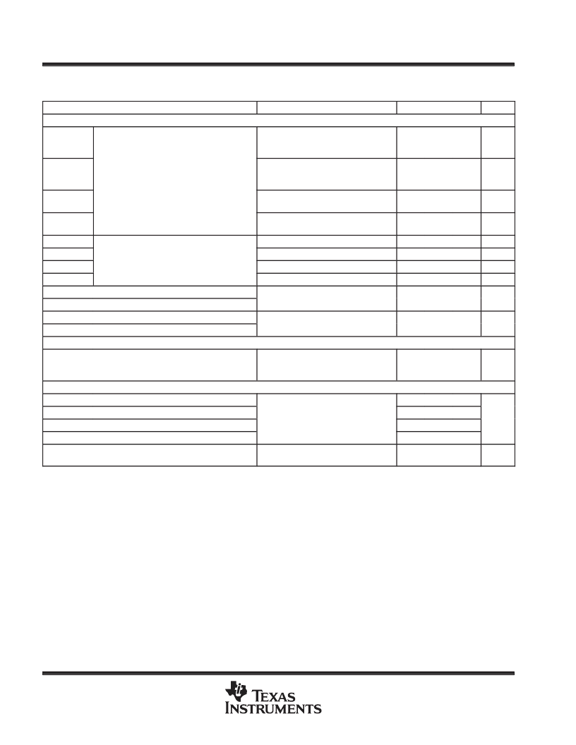
electrical characteristics over recommended operating free-air temperature range, 0 < T
J
< 125
°
C,
V
IN
= 4.3 V – 28 V (see test circuits) (unless otherwise noted) (continued)
PARAMETER
TEST CONDITIONS
MIN
TYP
MAX
UNIT
Output Drivers (see Note 4)
IO(srcTG)
Duty cycle < 2%, tpw < 100
μ
s,
V(BOOT) – V(PH) = 4.5 V,
V(TG) – V(PH) = 0.5 V (src)
Duty cycle < 2%, tpw < 100
μ
s,
V(BOOT) – V(PH) = 4.5 V,
V(TG) – V(PH) = 4 V (sink)
Duty cycle < 2%, tpw < 100
μ
s,
VCC = 4.5 V, V(BG) = 0.5 V (src)
Duty cycle < 2%, tpw < 100
μ
s,
VCC = 4.5 V, V(BG) = 4 V (src)
V(BOOT) – V(PH) = 4.5 V, VTG = 4 V
V(BOOT) – V(PH) = 4.5 V, VTG = 0.5 V
VCC = 4.5 V, V(BG) = 4 V
VCC = 4.5 V, V(BG) = 0.5 V
Cl = 3.3 nF, V(BOOT) = 4.5 V,
V(PH) = GND
1.2
2
A
IO(sinkTG)
Peak output current (see Notes 2 and 4)
1.2
3.3
A
IO(srcBG)
1.4
2
A
IO(sinkBG)
1.3
3.3
A
ro(srcTG)
ro(sinkTG)
ro(srcBG)
ro(sinkBG)
tf(TG)
tr(TG)
tf(BG)
tr(BG)
High-Side DRIVER Quiescent Current
2.5
Output resistance (see Note 4)
1.5
2.5
1.5
TG fall time (AC) (see Note 5)
10
ns
TG rise time (AC) (see Note 5)
BG fall time (AC) (see Note 5)
Cl = 3.3 nF, VCC = 4.5 V
3 3 nF V
4 5 V
10
ns
BG rise time (AC) (see Note 5)
Ihighdrq1
HIGHDRIVE (TG) quiescent current
VR_ON grounded, or VCC below
UVLO threshold;
V(BOOT) = 5 V,
PH grounded
10
μ
A
Adaptive Deadtime Circuit
VIH(TG)
VIL(TG)
VIH(BG)
VIL(BG)
TG – PH High-level input voltage
2.4
TG – PH Low-level input voltage
V(IS–) = 0.925 V – 2 V (see Note 2)
0 925 V
1.33
V
BG High-level input voltage
3
BG Low-level input voltage
1.7
t(NUL)
Driver nonoverlap time (AC)
CBG = 9 nF, 10% threshold on BG,
VCC = 5 V
50
ns
NOTES:
2. Ensured by design, not production tested.
4. The pulldown (sink) circuit of the high-side driver is a MOSFET transistor referenced to DRVGND. The driver circuits are bipolar
and MOSFET transistors in parallel. The peak output current rating is the combined current rating from the bipolar and MOSFET
transistors. The output resistance is the rds(on) of the MOSFET transistor when the voltage on the driver output is less than the
saturation voltage of the bipolar transistor.
5. Rise and fall times are measured from 10% to 90% of pulsed values.
P
相關PDF資料 |
PDF描述 |
|---|---|
| TPS535G7 | PHOTOVOLTAIC CELL FOR THERMOPILE DETECTION |
| TPS535G9 | PHOTOVOLTAIC CELL FOR THERMOPILE DETECTION |
| TPS54611PWP | Analog IC |
| TPS54611PWPR | Analog IC |
| TPS54612PWP | Analog IC |
相關代理商/技術參數(shù) |
參數(shù)描述 |
|---|---|
| TPS535G7 | 制造商:未知廠家 制造商全稱:未知廠家 功能描述:PHOTOVOLTAIC CELL FOR THERMOPILE DETECTION |
| TPS535G9 | 制造商:未知廠家 制造商全稱:未知廠家 功能描述:PHOTOVOLTAIC CELL FOR THERMOPILE DETECTION |
| TPS53622RSBT | 功能描述:FET CONTROLLER 制造商:texas instruments 系列:* 包裝:剪切帶(CT) 零件狀態(tài):在售 安裝類型:表面貼裝 封裝/外殼:40-WFQFN 裸露焊盤 供應商器件封裝:40-WQFN(5x5) 標準包裝:1 |
| TPS53624RHAR | 功能描述:DC/DC 開關控制器 Dual Phase D-CAP Buck Reg RoHS:否 制造商:Texas Instruments 輸入電壓:6 V to 100 V 開關頻率: 輸出電壓:1.215 V to 80 V 輸出電流:3.5 A 輸出端數(shù)量:1 最大工作溫度:+ 125 C 安裝風格: 封裝 / 箱體:CPAK |
| TPS53624RHAT | 功能描述:DC/DC 開關控制器 Dual Phase D-CAP Buck Reg RoHS:否 制造商:Texas Instruments 輸入電壓:6 V to 100 V 開關頻率: 輸出電壓:1.215 V to 80 V 輸出電流:3.5 A 輸出端數(shù)量:1 最大工作溫度:+ 125 C 安裝風格: 封裝 / 箱體:CPAK |
發(fā)布緊急采購,3分鐘左右您將得到回復。