- 您現(xiàn)在的位置:買賣IC網(wǎng) > PDF目錄382679 > TPS535G1 PHOTOVOLTAIC CELL FOR THERMOPILE DETECTION PDF資料下載
參數(shù)資料
| 型號: | TPS535G1 |
| 英文描述: | PHOTOVOLTAIC CELL FOR THERMOPILE DETECTION |
| 中文描述: | 光伏電池的熱電堆檢測 |
| 文件頁數(shù): | 6/16頁 |
| 文件大小: | 231K |
| 代理商: | TPS535G1 |

TPS5300
IMVP MOBILE POWER SUPPLY CONTROLLER
SLVS334 – DECEMBER 2000
6
POST OFFICE BOX 655303
DALLAS, TEXAS 75265
electrical characteristics over recommended operating free-air temperature range, 0 < T
J
< 125
°
C,
V
IN
= 4.3 V – 28 V (unless otherwise noted) (continued)
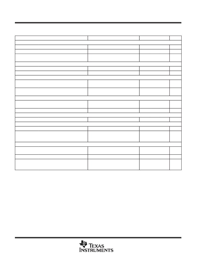
PARAMETER
TEST CONDITIONS
MIN
TYP
MAX
UNIT
Bias UVLO (Resets fault latch)
VIT(startUVLO)
VIT(stopUVLO)
Start threshold
4.46
V
Stop threshold
3.3
V
VBIAS quiescent current, I(ving1)
VR_ON connected to GND and VI above
UVLO start threshold
10
15
μ
A
VR_ON UVLO (Resets fault latch)
VIT(startVRON)
VIT(stopVRON)
Slowstart
Start threshold
2.1
2.5
V
Stop threshold
1.3
V
I(chg)
Charge current (I(chg) = (I(REFB)/5)
V(SS) = 0.5 V, I(VREFB) = 65
μ
A VREFB
= 1.3 V; I(chg) = (I(VREFB)/5)
V(SS) = 1.3 V,
Design for VIN(min) = 4.5 V
10.4
13
15.6
μ
A
I(dischg)
Discharge current
3
mA
VGATE (CORE, IO, CLK) (PWRGD of three outputs with open drain output)
V(VGATE)
Undervoltage trip point
(VSENSE_CORE, _IO, & _CLK)
VIN and V(drv) above UVLO thresholds
87.5
90
92.5
%Vref
V(olVGATE)
Enable EXT (SHUTDOWNB of IC with open-drain output. Use pullup resistor to 5 V or 3.3 V)
Output saturation voltage
IO = 2.5 mA
0.5
0.75
V
V(olEN_EXT)
DROOP Compensation
Output saturation voltage
IO = 2.5 mA
0.5
0.75
V
V(DROOP_ACC)
Initial accuracy
V(DROOP) = 50 mV
15-mV to 150-mV swing,
1.3 V
≤
Vref
≤
3.3 V, VCC = 5 V
(see Note 2)
–4
8
mV
tPHL(HC)
Propagation delay
200
500
ns
Current Sensing
G(CS)
Gain
With chopper stabilization (backup dis-
able with metal mask)
24
25
26
V/V
VIO
Input offset
VIS– = 1.3 V, VIS+ – VIS– = 10 mV
VIS– = 0.925 V – 2 V, VIS+ is pulsed from
VIS– to (VIS– + 50 mV),
VCC = 5 V (see Note 2)
–3
3
mV
t(VDSRESP)
Response time (measured from 50% of
(VIS+ – VIS– ) to 50% of V(IOUT))
500
ns
NOTES:
2. Ensured by design, not production tested.
3. The VBIAS voltage is required to be a quiet bias supply for the TPS5300 control logic. External noisy loads should use VCC instead
of the VBIAS voltage.
P
相關(guān)PDF資料 |
PDF描述 |
|---|---|
| TPS535G10 | PHOTOVOLTAIC CELL FOR THERMOPILE DETECTION |
| TPS535G14 | PHOTOVOLTAIC CELL FOR THERMOPILE DETECTION |
| TPS535G2 | PHOTOVOLTAIC CELL FOR THERMOPILE DETECTION |
| TPS535G20 | PHOTOVOLTAIC CELL FOR THERMOPILE DETECTION |
| TPS535G4 | PHOTOVOLTAIC CELL FOR THERMOPILE DETECTION |
相關(guān)代理商/技術(shù)參數(shù) |
參數(shù)描述 |
|---|---|
| TPS535G10 | 制造商:未知廠家 制造商全稱:未知廠家 功能描述:PHOTOVOLTAIC CELL FOR THERMOPILE DETECTION |
| TPS535G14 | 制造商:未知廠家 制造商全稱:未知廠家 功能描述:PHOTOVOLTAIC CELL FOR THERMOPILE DETECTION |
| TPS535G2 | 制造商:未知廠家 制造商全稱:未知廠家 功能描述:PHOTOVOLTAIC CELL FOR THERMOPILE DETECTION |
| TPS535G20 | 制造商:未知廠家 制造商全稱:未知廠家 功能描述:PHOTOVOLTAIC CELL FOR THERMOPILE DETECTION |
| TPS535G4 | 制造商:未知廠家 制造商全稱:未知廠家 功能描述:PHOTOVOLTAIC CELL FOR THERMOPILE DETECTION |
發(fā)布緊急采購,3分鐘左右您將得到回復。