- 您現(xiàn)在的位置:買賣IC網(wǎng) > PDF目錄384026 > TPA3000D1 (Texas Instruments, Inc.) 17-W MONO FILTER-FREE CLASS-D AUDIO POWER AMPLIFIER PDF資料下載
參數(shù)資料
| 型號: | TPA3000D1 |
| 廠商: | Texas Instruments, Inc. |
| 英文描述: | 17-W MONO FILTER-FREE CLASS-D AUDIO POWER AMPLIFIER |
| 中文描述: | 17單聲道無濾波器D類音頻功率放大器 |
| 文件頁數(shù): | 3/19頁 |
| 文件大小: | 273K |
| 代理商: | TPA3000D1 |
TPA3000D1
SLOS379A
–
SEPTEMBER 2001
–
REVISED JANUARY 2002
3
www.ti.com
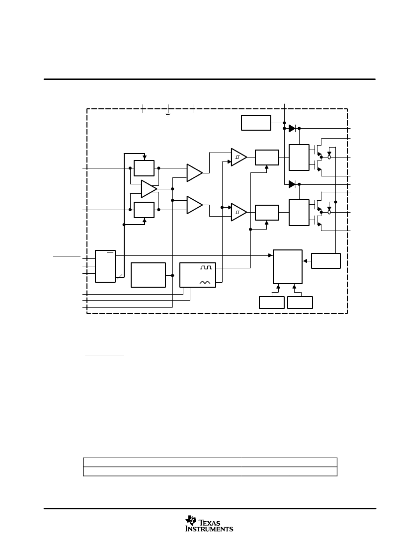
functional block diagram
Gate
Drive
_
+
Gate
Drive
_
+
_
+
_
Gain
Adjust
Gain
Adjust
Start-Up
Protection
Logic
OC
Detect
Thermal
VCC OK
Ramp
Generator
Biases
and
References
Gain
2
AGND
VREF
VREF
PVCC
INN
OUTN
PGND
PVCC
OUTP
PGND
INP
SHUTDOWN
GAIN1
GAIN0
COSC
ROSC
BYPASS
SD
_
+
_
+
Deglitch
Logic
Deglitch
Logic
VCC
VCC
BSP
BSN
Clamp
Reference
VCLAMP
Short-circuit protection operates only for shorts from the outputs to ground.
absolute maximum ratings over operating free-air temperature range (unless otherwise noted)
Supply voltage: V
CC,
PV
CC
Input voltage: SHUTDOWN
GAIN0, GAIN1
INN, INP
Continuous total power dissipation
Operating free-air temperature range, T
A
Operating junction temperature range, T
J
Storage temperature range, T
stg
Lead temperature 1,6 mm (1/16 inch) from case for 10 seconds
–
0.3 V to 21 V
. . . . . . . . . . . . . . . . . . . . . . . . . . . . . . . . . . . . . . . . . . . . . . . . . . . . . . . . . . . . .
. . . . . . . . . . . . . . . . . . . . . . . . . . . . . . . . . . . . . . . . . . . . . . . . . . . . . . . .
. . . . . . . . . . . . . . . . . . . . . . . . . . . . . . . . . . . . . . . . . . . . . . . . . . . . . . . . . . . . .
. . . . . . . . . . . . . . . . . . . . . . . . . . . . . . . . . . . . . . . . . . . . . . . . . . . . . . . . . . . . . . . . . .
. . . . . . . . . . . . . . . . . . . . . . . . . . . . . . . . . . . . . . . . .
. . . . . . . . . . . . . . . . . . . . . . . . . . . . . . . . . . . . . . . . . . . . . . . . . .
. . . . . . . . . . . . . . . . . . . . . . . . . . . . . . . . . . . . . . . . . . . . . . . .
. . . . . . . . . . . . . . . . . . . . . . . . . . . . . . . . . . . . . . . . . . . . . . . . . . . . . . . .
–
0.3 V to V
CC
+ 0.3 V
–
0.3 V to 5.5 V
–
0.3 V to 7 V
(see Dissipation Rating Table)
–
40
°
C to 85
°
C
–
40
°
C to 150
°
C
–
65
°
C to 150
°
C
260
°
C
. . . . . . . . . . . . . . . . . . . . . . . . . . . . . . . . . . . . .
Stresses beyond those listed under
“
absolute maximum ratings
”
may cause permanent damage to the device. These are stress ratings only, and
functional operation of the device at these or any other conditions beyond those indicated under
“
recommended operating conditions
”
is not
implied. Exposure to absolute-maximum-rated conditions for extended periods may affect device reliability.
DISSIPATION RATING TABLE
PACKAGE
TA
≤
25
°
C
2.7 W
DERATING FACTOR
21.8 mW/
°
C
TA = 70
°
C
1.7 W
TA = 85
°
C
1.4 W
PWP
相關PDF資料 |
PDF描述 |
|---|---|
| TPA3101D2_07 | 10-W STEREO CLASS-D AUDIO POWER AMPLIFIER |
| TPA4411M | 80-mW DIRECTPATH STEREO HEADPHONE DRIVER |
| TPA4411MRTJ | 80-mW DIRECTPATH STEREO HEADPHONE DRIVER |
| TPA5051_07 | FOUR CHANNEL DIGITAL AUDIO LIP-SYNC DELAY WITH I2C CONTROL |
| TPIC2701M | 7-CHANNEL COMMON-SOURCE POWER DMOS ARRAY |
相關代理商/技術參數(shù) |
參數(shù)描述 |
|---|---|
| TPA3000D1APWP | 制造商:Rochester Electronics LLC 功能描述:- Bulk |
| TPA3000D1APWPR | 制造商:Texas Instruments 功能描述: |
| TPA3000D1EVM | 制造商:Texas Instruments 功能描述:TPA3000D1 AUDIO PWR AMPLIFIER EVM - Bulk |
| TPA3000D1PWP | 制造商:Rochester Electronics LLC 功能描述:- Bulk |
| TPA3000D1PWPR | 制造商:未知廠家 制造商全稱:未知廠家 功能描述:AUDIO AMPLIFIER|SINGLE|CMOS|TSSOP|20PIN|PLASTIC |
發(fā)布緊急采購,3分鐘左右您將得到回復。