- 您現(xiàn)在的位置:買賣IC網(wǎng) > PDF目錄98270 > TPA2008D2PWPRG4 (TEXAS INSTRUMENTS INC) 2 CHANNEL(S), VOLUME CONTROL CIRCUIT, PDSO24 PDF資料下載
參數(shù)資料
| 型號: | TPA2008D2PWPRG4 |
| 廠商: | TEXAS INSTRUMENTS INC |
| 元件分類: | 音頻控制 |
| 英文描述: | 2 CHANNEL(S), VOLUME CONTROL CIRCUIT, PDSO24 |
| 封裝: | GREEN, PLASTIC, HTSSOP-24 |
| 文件頁數(shù): | 8/26頁 |
| 文件大小: | 691K |
| 代理商: | TPA2008D2PWPRG4 |
www.ti.com
VOLUME CONTROL OPERATION
2
0
2
2.41
2.44
2.50
2.53
Gain
dB
Voltage on VOLUME Pin V
Decreasing Voltage on
VOLUME Terminal
Increasing Voltage on
VOLUME Terminal
SPECIAL LAYOUT CONSIDERATIONS
TPA2008D2
SLOS413C – JULY 2003 – REVISED MAY 2004
APPLICATION INFORMATION (continued)
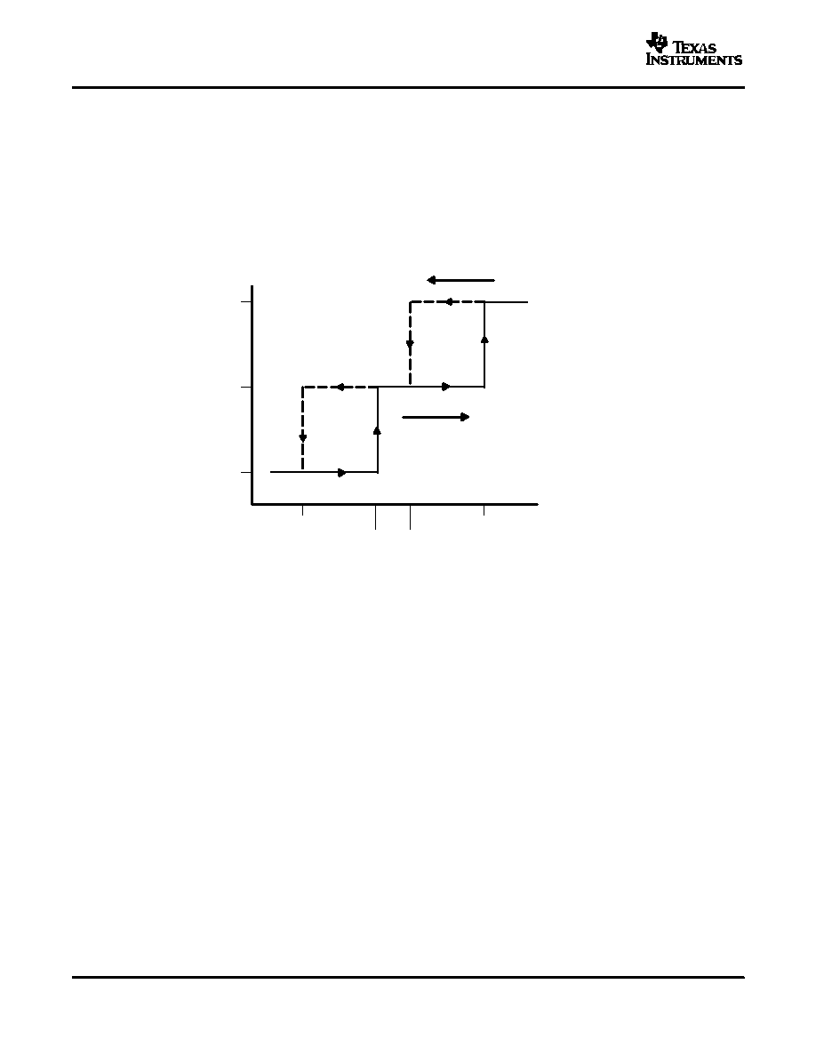
The VOLUME pin controls the volume of the TPA2008D2. It is controlled with a dc voltage, which should not
exceed VDD. Table 1 lists the voltage on the VOLUME pin and the corresponding gain.
The trip point, where the gain actually changes, is different depending on whether the voltage on the VOLUME
terminal is increasing or decreasing as a result of hysteresis about each trip point. The hysteresis ensures that
the gain control is monotonic and does not oscillate from one gain step to another. A pictorial representation of
the volume control can be found in Figure 19. The graph focuses on three gain steps with the trip points defined
in the first and second columns of Table 1. The dotted lines represent the hysteresis about each gain step.
Figure 19. DC Volume Control Operation
The voltage on the VOLUME pin must closely track that of the supply voltage, VDD. As the output power is
increased, the noise on the power supply will increase. The noise seen by the PVDD pin must also be seen by the
VOLUME pin. It is for that reason that absolutely no capacitor should be placed on the VOLUME pin. Additional
steps should be taken to reduce the line capacitance on the VOLUME pin, such as reducing line length. Any
capacitance on the VOLUME pin will act as a filter, thus making the voltage seen by the VOLUME pin and VDD
different. If the difference is large enough, the amplifier will change gain steps.
A star point should be used for power, where the supply voltage for VDD, PVDD, and the volume circuitry can be
taken. This point is typically at the bulk decoupling capacitor. The trace connecting the star point to a
potentiometer or a DAC should be short. The trace connecting the potentiometer or DAC to the VOLUME pin
should be kept as short and straight as possible.
As with the VDD, a star ground should likewise be used. There should exist on the board a point where AGND
and PGND converge. This should be the only place where the two grounds are connected. The ground used for
the volume control should be AGND. If a potentiometer is to be used to control the volume of the device, it
should be connected to AGND. A DAC that has a ground reference should have a short trace to AGND from its
ground reference input.
For an example of proper board layout, please refer to the TPA2008D2 EVM User's Guide, document number
SLOU116.
16
相關(guān)PDF資料 |
PDF描述 |
|---|---|
| TPA2010D1YEFR | 2.5 W, 2 CHANNEL, AUDIO AMPLIFIER, PBGA9 |
| TPA2010D1YEFT | 2.5 W, 2 CHANNEL, AUDIO AMPLIFIER, PBGA9 |
| TPA2010D1YZFR | 2.5 W, 2 CHANNEL, AUDIO AMPLIFIER, PBGA9 |
| TPA2010D1YZFT | 2.5 W, 2 CHANNEL, AUDIO AMPLIFIER, PBGA9 |
| TPA2010D1YEF | 2.5 W, 1 CHANNEL, AUDIO AMPLIFIER, BGA9 |
相關(guān)代理商/技術(shù)參數(shù) |
參數(shù)描述 |
|---|---|
| TPA200RL | 功能描述:TVS 二極管 - 瞬態(tài)電壓抑制器 200V 50uA Bidirect RoHS:否 制造商:Vishay Semiconductors 極性:Bidirectional 工作電壓: 擊穿電壓:58.9 V 鉗位電壓:77.4 V 峰值浪涌電流:38.8 A 系列: 封裝 / 箱體:DO-214AB 最小工作溫度:- 55 C 最大工作溫度:+ 150 C |
| TPA2010 | 制造商:TI 功能描述:2.5-W high efficiency filter-free class-D audio power amplifier |
| TPA2010D1 | 制造商:Texas Instruments 功能描述:Audio Amp Mono 2.5W Class-D TPA2010D1 制造商:TI 功能描述:2.5-W MONO FILTER-FREE CLASS-D AUDIO POWER AMPLIFIER |
| TPA2010D1_06 | 制造商:TI 制造商全稱:Texas Instruments 功能描述:2.5-W MONO FILTER-FREE CLASS-D AUDIO POWER AMPLIFIER |
| TPA2010D1EVM | 功能描述:音頻 IC 開發(fā)工具 TPA2010D1 Eval Mod RoHS:否 制造商:Texas Instruments 產(chǎn)品:Evaluation Kits 類型:Audio Amplifiers 工具用于評估:TAS5614L 工作電源電壓:12 V to 38 V |
發(fā)布緊急采購,3分鐘左右您將得到回復。