- 您現(xiàn)在的位置:買賣IC網(wǎng) > PDF目錄384025 > TP13064B (Texas Instruments, Inc.) MONOLITHIC SERIAL INTERFACE COMBINED PCM CODEC AND FILTER PDF資料下載
參數(shù)資料
| 型號: | TP13064B |
| 廠商: | Texas Instruments, Inc. |
| 元件分類: | Codec |
| 英文描述: | MONOLITHIC SERIAL INTERFACE COMBINED PCM CODEC AND FILTER |
| 中文描述: | 整體式串行接口的PCM編解碼器和過濾器 |
| 文件頁數(shù): | 17/21頁 |
| 文件大?。?/td> | 300K |
| 代理商: | TP13064B |
TP3064B, TP3067B, TP13064B, TP13067B
MONOLITHIC SERIAL INTERFACE
COMBINED PCMCODEC AND FILTER
SCTS031D – MAY 1990 –REVISED JULY 1996
17
POST OFFICE BOX 655303
DALLAS, TEXAS 75265
PRINCIPALS OF OPERATION
transmit section
The transmit section input is an operational amplifier with provision for gain adjustment using two external
resistors. Gains in excess of 20 dB across the audio pass band are possible via low noise and wide bandwidth.
The operational amplifier drives a unity-gain filter consisting of an RC active prefilter followed by an eight-order
switched-capacitor band-pass filter clocked at 256 kHz. The output of this filter directly drives the encoder
sample-and-hold circuit. As per
μ
-law (TP3064B and TP13064B) or A-law (TP3067B and TP13067B) coding
conventions, the ADC is a companding type. A precision voltage reference provides a input overload of
nominally 2.5-V peak. The sampling of the filter output is controlled by the FSX frame-sync pulse. Then the
successive-approximation encoding cycle begins. The 8-bit code is loaded into a buffer and shifted out through
DX at the next FSX pulse. The total encoding delay is approximately 290
μ
s. Any offset voltage due to the filters
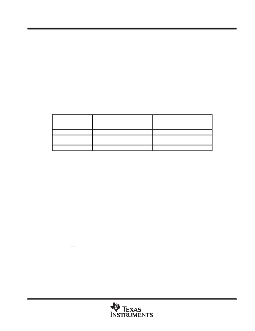
or comparator is cancelled by sign bit integration (see Table 2).
Table 2. Encoding Format at DX Output
TP3064B, TP13064B
μ
-LAW
TP3067B, TP13067B
A-LAW
(INCLUDES EVEN-BIT INVERSION)
VI = + Full scale
1 0 0 0 0 0 0 0
1 0 1 0 1 0 1 0
VI = 0
1 1 1 1 1 1 1 1
0 1 1 1 1 1 1 1
1 1 0 1 0 1 0 1
0 1 0 1 0 1 0 1
VI = – Full scale
0 0 0 0 0 0 0 0
0 0 1 0 1 0 1 0
receive section
The receive section consists of an expanding DAC that drives a fifth-order low-pass filter clocked at 256 kHz.
The decoder is
μ
-law (TP3064B and TP13064B) or A-law (TP3067B and TP13067B) and the fifth-order
low-pass filter corrects for the (sin x)/x attenuation caused by the 8-kHz sample/hold. The filter is followed by
a second-order RC active post-filter with its output at VFRO. The receive section is unity-gain but gain can be
added by using the power amplifiers. At FSR, the data at DR is clocked in on the falling edge of the next eight
BCLKR (BCLKX) periods. At the end of the decoder time slot, the decoding cycle begins and 10
μ
s later the
decoder DAC output is updated. The decoder delay is about 10
μ
s (decoder update) plus 110
μ
s (filter delay)
plus 62.5
μ
s (1/2 frame), or a total of approximately180
μ
s.
receive power amplifiers
Two inverting-mode power amplifiers are provided for directly driving a match-line interface transformer. The
gain of the first power amplifier can be adjusted to boost the
±
2.5-V peak output signal from the receive filter
up to the
±
3.3-V peak into an unbalanced 300-
load, or
±
4 V into an unbalanced 15-k
load. The second power
amplifier is internally connected in unity-gain inverting mode to give 6-dB signal gain for balanced loads.
Maximum power transfer to a 600-
subscriber line termination is obtained by differentially driving a balanced
transformer with
√
2:1 turns ratio, as shown in Figure 3. A total peak power of 15.6 dBm can be delivered to the
load plus termination.
相關(guān)PDF資料 |
PDF描述 |
|---|---|
| TP13064BDW | MONOLITHIC SERIAL INTERFACE COMBINED PCM CODEC AND FILTER |
| TP13064BN | MONOLITHIC SERIAL INTERFACE COMBINED PCM CODEC AND FILTER |
| TP13067B | MONOLITHIC SERIAL INTERFACE COMBINED PCM CODEC AND FILTER |
| TPA0102(中文) | 300-Milliwatt Stereo Audio Power AMP(兩通道立體聲橋式或單端音頻功放) |
| TPA0103PWP(中文) | 3-Channel Audio Power AMP(1路橋式,兩路單端音頻功放) |
相關(guān)代理商/技術(shù)參數(shù) |
參數(shù)描述 |
|---|---|
| TP13064BDW | 功能描述:接口—CODEC PCM CODEC RoHS:否 制造商:Texas Instruments 類型: 分辨率: 轉(zhuǎn)換速率:48 kSPs 接口類型:I2C ADC 數(shù)量:2 DAC 數(shù)量:4 工作電源電壓:1.8 V, 2.1 V, 2.3 V to 5.5 V 最大工作溫度:+ 85 C 安裝風(fēng)格:SMD/SMT 封裝 / 箱體:DSBGA-81 封裝:Reel |
| TP13064BDWR | 功能描述:接口—CODEC Mono Serial Intfc PCM Codec/Filter RoHS:否 制造商:Texas Instruments 類型: 分辨率: 轉(zhuǎn)換速率:48 kSPs 接口類型:I2C ADC 數(shù)量:2 DAC 數(shù)量:4 工作電源電壓:1.8 V, 2.1 V, 2.3 V to 5.5 V 最大工作溫度:+ 85 C 安裝風(fēng)格:SMD/SMT 封裝 / 箱體:DSBGA-81 封裝:Reel |
| TP13064BJ | 制造商:未知廠家 制造商全稱:未知廠家 功能描述:u-Law CODEC |
| TP13064BN | 制造商:TI 制造商全稱:Texas Instruments 功能描述:MONOLITHIC SERIAL INTERFACE COMBINED PCM CODEC AND FILTER |
| TP13067A | 制造商:TI 制造商全稱:Texas Instruments 功能描述:MONOLITHIC SERIAL INTERFACE COMBINED PCM CODEC AND FILTER |
發(fā)布緊急采購,3分鐘左右您將得到回復(fù)。