- 您現(xiàn)在的位置:買(mǎi)賣(mài)IC網(wǎng) > PDF目錄97769 > TMXP262 (TEMEX COMPONENTS) 1 FUNCTIONS, 71 MHz, SAW FILTER PDF資料下載
參數(shù)資料
| 型號(hào): | TMXP262 |
| 廠商: | TEMEX COMPONENTS |
| 元件分類(lèi): | 聲表面波濾波器 |
| 英文描述: | 1 FUNCTIONS, 71 MHz, SAW FILTER |
| 文件頁(yè)數(shù): | 1/3頁(yè) |
| 文件大小: | 188K |
| 代理商: | TMXP262 |
September 23rd, 2003
TMX P262
SAW BANDPASS FILTER – BASE STATION GSM – IF
Preliminary Specification (Rev 4)
1
T
E
ME
X
re
se
rv
e
st
he
ri
ght
to
mo
di
fy
her
ei
n
s
p
eci
fic
ati
ons
and
in
fo
rm
ati
on
a
ta
n
ytime
w
h
en
n
e
ce
ssar
yto
p
ro
vi
de
o
p
tim
um
p
er
for
m
ance
and
cos
t.
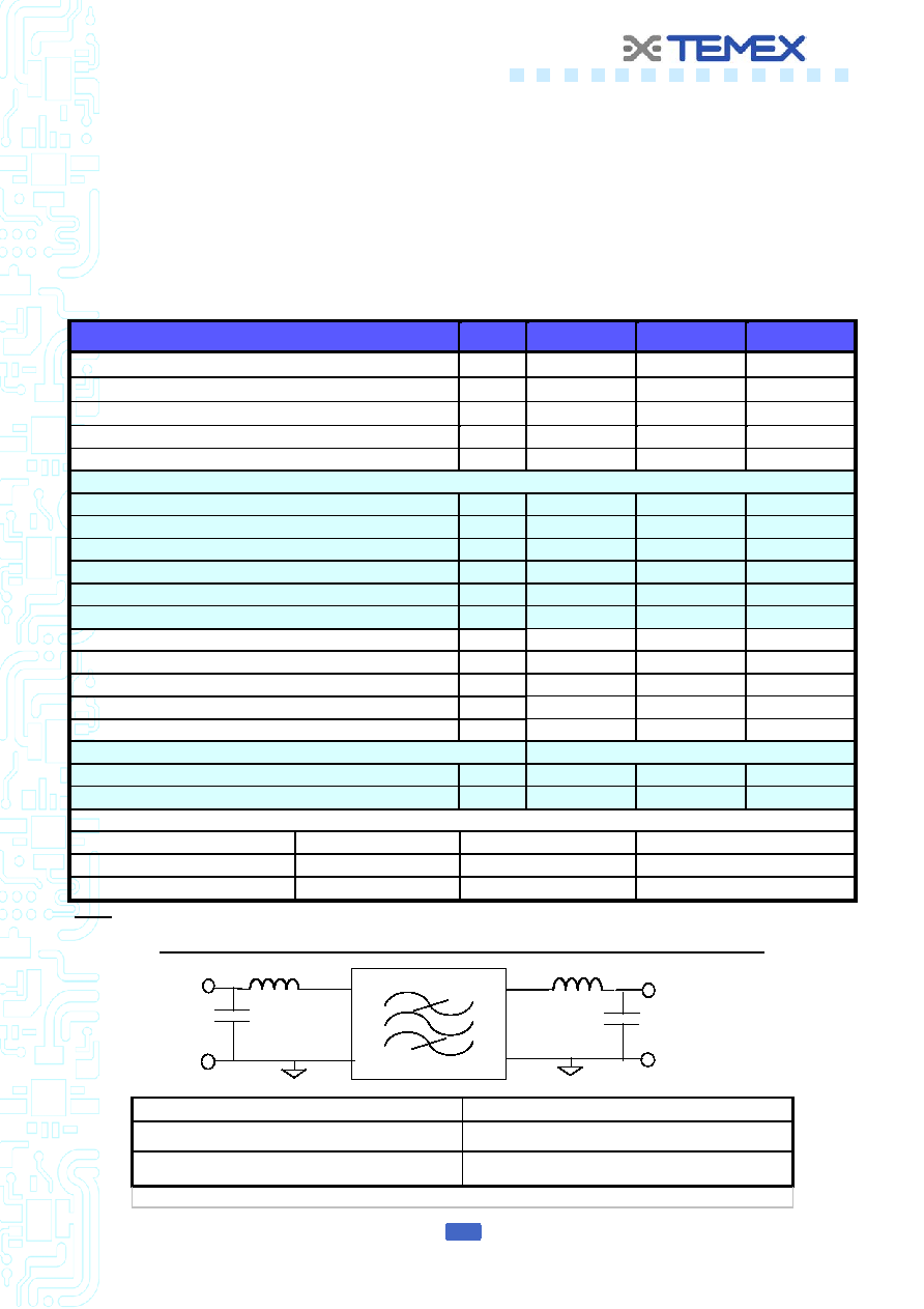
Operating Temperature range : [-5°C ; +80°C]
Electrical Parameters
Unit
Minimum
Typical
Maximum
Source Impedance (single ended)
(1)
-
50
-
Load Impedance (single)
(1)
-
50
-
Center Frequency fo
MHz
70.975
71.000
71.025
Bandwidth at –1.5 dB
MHz
0.16
0.30
-
Bandwidth at –3.0 dB
MHz
0.20
0.35
-
Template on the amplitude, reference is loss at fo
Attenuation at fo ± 0.2 MHz
dB
3
14
-
Attenuation at fo ± 0.4 MHz
dB
25
30
-
Attenuation at frequency < 69.9 MHz
dB
42
45
-
Attenuation from 69.9 MHz to 70.4 MHz
dB
40
43
Attenuation from 71.6 MHz to 71.8 MHz
dB
37
41
Attenuation at frequency > 71.8 MHz
dB
38
43
-
Insertion Loss at fo
dB
-
6.6
8
Amplitude ripple within fo ± 0.08 MHz
dB p-p
0.8
1.5
Average delay within fo ± 0.08 MHz
s
-
2.7
3
Group delay Variation within fo ± 0.08 MHz
ns p-p
-
300
1000
Input and Output Return Losses at fo
dB
10
12
-
Package type & size
SMP 08
Length x Width
mm
-
14.0 x 8.0
-
Height
mm
-
2.0
Pin Out
Input
1
Output
6
Input Return
10
Output return
5
Case Ground
2,3,4,7,8,9
To Be Grounded
2,3,4,5,7,8,9,10
Notes :
(1) With matching network
MATCHING NETWORK FOR 50
SINGLE / 50 SINGLE CONFIGURATION
Temex Test Fixture
Customer PC Board
L1 = 470 nH + 47 nH, Q > 40
C1 = 47 pF + 15 pF
L1 = TBD ± 2% ; Q > 40
C1 = TBD ± 2%
L2 = 390 nH + 56 nH, Q > 40
C2 = 47 pF + 5.6 pF
L2 = TBD ± 2% ; Q > 40
C2 = TBD ± 2%
TBD = To Be Defined on customer PC Board
L1
L2
Input
50
Single Ended
Output
50
Single Ended
1
10
6
5
C1
C2
GND
相關(guān)PDF資料 |
PDF描述 |
|---|---|
| TMXP310 | 1 FUNCTIONS, 220.38 MHz, SAW FILTER |
| TMXP574 | 1 FUNCTIONS, 260 MHz, SAW FILTER |
| TMXP654 | 1 FUNCTIONS, 374 MHz, SAW FILTER |
| TMXR009 | 1 FUNCTIONS, 1765 MHz, SAW FILTER |
| TMXR038 | 1 FUNCTIONS, 1842.5 MHz, SAW FILTER |
相關(guān)代理商/技術(shù)參數(shù) |
參數(shù)描述 |
|---|---|
| TMXS142 | 制造商:未知廠家 制造商全稱(chēng):未知廠家 功能描述:SAW BANDPASS FILTER |
| TMXT504 | 制造商:未知廠家 制造商全稱(chēng):未知廠家 功能描述:SAW BANDPASS FILTER |
| TMXTA02 | 制造商:TEMEX 制造商全稱(chēng):TEMEX 功能描述:SAW Bandpass Filter - DVB-C - RF |
| TMXTA03 | 制造商:TEMEX 制造商全稱(chēng):TEMEX 功能描述:SAW Bandpass Filter - DVB-C - RF |
| TMXTA04 | 制造商:TEMEX 制造商全稱(chēng):TEMEX 功能描述:SAW Bandpass Filter - Remote Control - RF |
發(fā)布緊急采購(gòu),3分鐘左右您將得到回復(fù)。