- 您現(xiàn)在的位置:買賣IC網(wǎng) > PDF目錄383957 > TLV2254AMJ (Texas Instruments, Inc.) Advanced LinCMOSE RAIL-TO-RAIL VERY LOW-POWER OPERATIONAL AMPLIFIERS PDF資料下載
參數(shù)資料
| 型號(hào): | TLV2254AMJ |
| 廠商: | Texas Instruments, Inc. |
| 元件分類: | 運(yùn)動(dòng)控制電子 |
| 英文描述: | Advanced LinCMOSE RAIL-TO-RAIL VERY LOW-POWER OPERATIONAL AMPLIFIERS |
| 中文描述: | 高級(jí)LinCMOSE軌至軌極低功耗運(yùn)算放大器 |
| 文件頁數(shù): | 5/60頁 |
| 文件大?。?/td> | 1218K |
| 代理商: | TLV2254AMJ |
第1頁第2頁第3頁第4頁當(dāng)前第5頁第6頁第7頁第8頁第9頁第10頁第11頁第12頁第13頁第14頁第15頁第16頁第17頁第18頁第19頁第20頁第21頁第22頁第23頁第24頁第25頁第26頁第27頁第28頁第29頁第30頁第31頁第32頁第33頁第34頁第35頁第36頁第37頁第38頁第39頁第40頁第41頁第42頁第43頁第44頁第45頁第46頁第47頁第48頁第49頁第50頁第51頁第52頁第53頁第54頁第55頁第56頁第57頁第58頁第59頁第60頁
TLV225x, TLV225xA
Advanced LinCMOS
RAIL-TO-RAIL
VERY LOW-POWER OPERATIONAL AMPLIFIERS
SLOS185C
–
FEBRUARY 1997
–
REVISED
–
MARCH 2001
5
POST OFFICE BOX 655303
DALLAS, TEXAS 75265
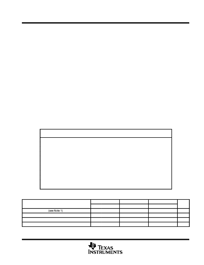
absolute maximum ratings over operating free-air temperature range (unless otherwise noted)
Supply voltage, V
DD
(see Note 1)
Differential input voltage, V
ID
(see Note 2)
Input voltage range, V
I
(any input, see Note 1)
Input current, I
I
(each input)
Output current, I
O
. . . . . . . . . . . . . . . . . . . . . . . . . . . . . . . . . . . . . . . . . . . . . . . . . . . . . . . . . . . . . . . . . . . . . . .
Total current into V
DD+
. . . . . . . . . . . . . . . . . . . . . . . . . . . . . . . . . . . . . . . . . . . . . . . . . . . . . . . . . . . . . . . . . .
Total current out of V
DD
–
. . . . . . . . . . . . . . . . . . . . . . . . . . . . . . . . . . . . . . . . . . . . . . . . . . . . . . . . . . . . . . . .
Duration of short-circuit current (at or below) 25
°
C (see Note 3)
Continuous total power dissipation
. . . . . . . . . . . . . . . . . . . . . . . . . . . . . . . . . . . . .
Operating free-air temperature range, T
A
: I Suffix
Q Suffix
M Suffix
Storage temperature range, T
stg
. . . . . . . . . . . . . . . . . . . . . . . . . . . . . . . . . . . . . . . . . . . . . . . . . . .
Lead temperature 1,6 mm (1/16 inch) from case for 10 seconds: D, N, P, and PW packages
16 V
±
V
DD
. . . . . . . . . . . . . . . . . . . . . . . . . . . . . . . . . . . . . . . . . . . . . . . . . . . . . . . . . . . .
. . . . . . . . . . . . . . . . . . . . . . . . . . . . . . . . . . . . . . . . . . . . . . . . . . .
. . . . . . . . . . . . . . . . . . . . . . . . . . . . . . . . . .
. . . . . . . . . . . . . . . . . . . . . . . . . . . . . . . . . . . . . . . . . . . . . . . . . . . . . . . . . . . . . . .
V
DD
–
–
0.3 V to V
DD+
±
5 mA
±
50 mA
±
50 mA
±
50 mA
unlimited
. . . . . . . . . . . . . . . . . . . . . . . . . . . . . .
See Dissipation Rating Table
. . . . . . . . . . . . . . . . . . . . . . . . . . . . . . . . . . .
. . . . . . . . . . . . . . . . . . . . . . . . . . . . . . . . . .
. . . . . . . . . . . . . . . . . . . . . . . . . . . . . . . . . .
–
40
°
C to 125
°
C
–
40
°
C to 125
°
C
–
55
°
C to 125
°
C
–
65
°
C to 150
°
C
. . . . . . .
. . . . . . .
260
°
C
300
°
C
J, JG, U, and W packages
Stresses beyond those listed under
“
absolute maximum ratings
”
may cause permanent damage to the device. These are stress ratings only, and
functional operation of the device at these or any other conditions beyond those indicated under
“
recommended operating conditions
”
is not
implied. Exposure to absolute-maximum-rated conditions for extended periods may affect device reliability.
NOTES:
1. All voltage values, except differential voltages, are with respect to VDD
–
.
2. Differential voltages are at the noninverting input with respect to the inverting input. Excessive current flows when input is brought
below VDD
–
–
0.3 V.
3. The output may be shorted to either supply. Temperature and/or supply voltages must be limited to ensure that the maximum
dissipation rating is not exceeded.
DISSIPATION RATING TABLE
PACKAGE
TA
≤
25
°
C
POWER RATING
DERATING FACTOR
ABOVE TA = 25
°
C
5.8 mW/
°
C
7.6 mW/
°
C
11.0 mW/
°
C
TA = 85
°
C
POWER RATING
TA = 125
°
C
POWER RATING
D
–
8
725 mW
377 mW
145 mW
D
–
14
950 mW
494 mW
190 mW
FK
1375 mW
715 mW
275 mW
J
1375 mW
11.0 mW/
°
C
8.4 mW/
°
C
715 mW
275 mW
JG
1050 mW
546 mW
210 mW
N
1150 mW
9.2 mW/
°
C
8.0 mW/
°
C
598 mW
230 mW
P
1000 mW
520 mW
200 mW
PW
–
8
525 mW
4.2 mW/
°
C
273 mW
105 mW
PW
–
14
700 mW
5.6 mW/
°
C
5.5 mW/
°
C
364 mW
140 mW
U
700 mW
370 mW
150 mW
W
700 mW
5.5 mW/
°
C
370 mW
150 mW
recommended operating conditions
TLV225xI
MIN
2.7
TLV225xQ
MIN
2.7
TLV225xM
MIN
2.7
UNIT
MAX
MAX
MAX
Supply voltage, VDD
Input voltage range, VI
Common-mode input voltage, VIC
Operating free-air temperature, TA
NOTE 1: All voltage values, except differential voltages, are with respect to VDD
–
.
16
16
16
V
VDD
–
VDD
–
–
40
VDD+
–
1.3
VDD+
–
1.3
125
VDD
–
VDD
–
–
40
VDD+
–
1.3
VDD+
–
1.3
125
VDD
–
VDD
–
–
55
VDD+
–
1.3
VDD+
–
1.3
125
V
V
°
C
相關(guān)PDF資料 |
PDF描述 |
|---|---|
| TLV2252MU | Advanced LinCMOSE RAIL-TO-RAIL VERY LOW-POWER OPERATIONAL AMPLIFIERS |
| TLV2254AMW | Advanced LinCMOSE RAIL-TO-RAIL VERY LOW-POWER OPERATIONAL AMPLIFIERS |
| TLV2254MFK | Advanced LinCMOSE RAIL-TO-RAIL VERY LOW-POWER OPERATIONAL AMPLIFIERS |
| TLV2254MJ | Advanced LinCMOSE RAIL-TO-RAIL VERY LOW-POWER OPERATIONAL AMPLIFIERS |
| TLV2254MW | Advanced LinCMOSE RAIL-TO-RAIL VERY LOW-POWER OPERATIONAL AMPLIFIERS |
相關(guān)代理商/技術(shù)參數(shù) |
參數(shù)描述 |
|---|---|
| TLV2254AMJB | 制造商:TI 制造商全稱:Texas Instruments 功能描述:Advanced LinCMOS RAIL-TO-RAIL VERY LOW-POWER POERATIONAL AMPLIFIERS |
| TLV2254AMW | 制造商:TI 制造商全稱:Texas Instruments 功能描述:Advanced LinCMOS RAIL-TO-RAIL VERY LOW-POWER POERATIONAL AMPLIFIERS |
| TLV2254AMWB | 制造商:TI 制造商全稱:Texas Instruments 功能描述:Advanced LinCMOS RAIL-TO-RAIL VERY LOW-POWER POERATIONAL AMPLIFIERS |
| TLV2254AQD | 功能描述:運(yùn)算放大器 - 運(yùn)放 LiNCMOS R R RoHS:否 制造商:STMicroelectronics 通道數(shù)量:4 共模抑制比(最小值):63 dB 輸入補(bǔ)償電壓:1 mV 輸入偏流(最大值):10 pA 工作電源電壓:2.7 V to 5.5 V 安裝風(fēng)格:SMD/SMT 封裝 / 箱體:QFN-16 轉(zhuǎn)換速度:0.89 V/us 關(guān)閉:No 輸出電流:55 mA 最大工作溫度:+ 125 C 封裝:Reel |
| TLV2254AQDG4 | 功能描述:運(yùn)算放大器 - 運(yùn)放 Quad Lo-Vltg Rail To-Rail Op Amp RoHS:否 制造商:STMicroelectronics 通道數(shù)量:4 共模抑制比(最小值):63 dB 輸入補(bǔ)償電壓:1 mV 輸入偏流(最大值):10 pA 工作電源電壓:2.7 V to 5.5 V 安裝風(fēng)格:SMD/SMT 封裝 / 箱體:QFN-16 轉(zhuǎn)換速度:0.89 V/us 關(guān)閉:No 輸出電流:55 mA 最大工作溫度:+ 125 C 封裝:Reel |
發(fā)布緊急采購,3分鐘左右您將得到回復(fù)。