- 您現(xiàn)在的位置:買賣IC網(wǎng) > PDF目錄383954 > TLE207xY (Texas Instruments, Inc.) EXCALIBUR LOW-NOISE HIGH-SPEED JFET-INPUT OPERATIONAL AMPLIFIERS PDF資料下載
參數(shù)資料
| 型號(hào): | TLE207xY |
| 廠商: | Texas Instruments, Inc. |
| 英文描述: | EXCALIBUR LOW-NOISE HIGH-SPEED JFET-INPUT OPERATIONAL AMPLIFIERS |
| 中文描述: | 神劍低噪聲高速JFET輸入運(yùn)算放大器 |
| 文件頁(yè)數(shù): | 9/77頁(yè) |
| 文件大小: | 1285K |
| 代理商: | TLE207XY |
第1頁(yè)第2頁(yè)第3頁(yè)第4頁(yè)第5頁(yè)第6頁(yè)第7頁(yè)第8頁(yè)當(dāng)前第9頁(yè)第10頁(yè)第11頁(yè)第12頁(yè)第13頁(yè)第14頁(yè)第15頁(yè)第16頁(yè)第17頁(yè)第18頁(yè)第19頁(yè)第20頁(yè)第21頁(yè)第22頁(yè)第23頁(yè)第24頁(yè)第25頁(yè)第26頁(yè)第27頁(yè)第28頁(yè)第29頁(yè)第30頁(yè)第31頁(yè)第32頁(yè)第33頁(yè)第34頁(yè)第35頁(yè)第36頁(yè)第37頁(yè)第38頁(yè)第39頁(yè)第40頁(yè)第41頁(yè)第42頁(yè)第43頁(yè)第44頁(yè)第45頁(yè)第46頁(yè)第47頁(yè)第48頁(yè)第49頁(yè)第50頁(yè)第51頁(yè)第52頁(yè)第53頁(yè)第54頁(yè)第55頁(yè)第56頁(yè)第57頁(yè)第58頁(yè)第59頁(yè)第60頁(yè)第61頁(yè)第62頁(yè)第63頁(yè)第64頁(yè)第65頁(yè)第66頁(yè)第67頁(yè)第68頁(yè)第69頁(yè)第70頁(yè)第71頁(yè)第72頁(yè)第73頁(yè)第74頁(yè)第75頁(yè)第76頁(yè)第77頁(yè)
TLE207x, TLE207xA, TLE207xY
EXCALIBUR LOW-NOISE HIGH-SPEED
JFET-INPUT OPERATIONAL AMPLIFIERS
SLOS181A – FEBRUARY 1997 – REVISED MARCH 2000
9
POST OFFICE BOX 655303
DALLAS, TEXAS 75265
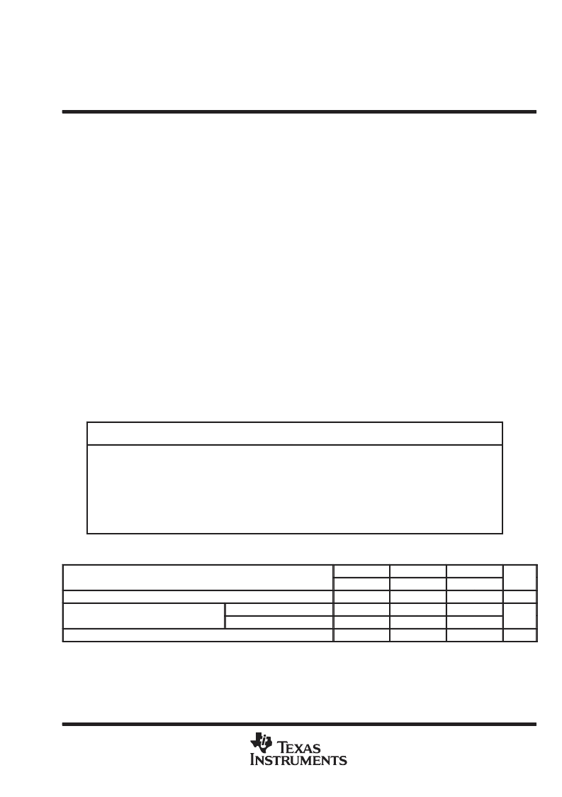
absolute maximum ratings over operating free-air temperature range (unless otherwise noted)
Supply voltage, V
CC+
(see Note 1)
Supply voltage, V
CC–
(see Note 1)
Differential input voltage range, V
ID
(see Note 2)
Input voltage range, V
I
(any input)
Input current, I
I
(each input)
Output current, I
O
(each output)
Total current into V
CC+
Total current out of V
CC–
Duration of short-circuit current at (or below) 25
°
C (see Note 3)
Continuous total dissipation
. . . . . . . . . . . . . . . . . . . . . . . . . . . . . . . . . . . . . . . . . . .
Operating free-air temperature range, T
A
: C suffix
19 V
–19 V
. . . . . . . . . . . . . . . . . . . . . . . . . . . . . . . . . . . . . . . . . . . . . . . . . . . . . . . . . . .
. . . . . . . . . . . . . . . . . . . . . . . . . . . . . . . . . . . . . . . . . . . . . . . . . . . . . . . . . .
. . . . . . . . . . . . . . . . . . . . . . . . . . . . . . . . . . . . . .
. . . . . . . . . . . . . . . . . . . . . . . . . . . . . . . . . . . . . . . . . . . . . . . . . . .
. . . . . . . . . . . . . . . . . . . . . . . . . . . . . . . . . . . . . . . . . . . . . . . . . . . . . . . . . . . . . . .
. . . . . . . . . . . . . . . . . . . . . . . . . . . . . . . . . . . . . . . . . . . . . . . . . . . . . . . . . .
. . . . . . . . . . . . . . . . . . . . . . . . . . . . . . . . . . . . . . . . . . . . . . . . . . . . . . . . . . . . . . . . . .
. . . . . . . . . . . . . . . . . . . . . . . . . . . . . . . . . . . . . . . . . . . . . . . . . . . . . . . . . . . . . . . .
V
CC+
to V
CC–
V
CC+
to V
CC–
±
1 mA
±
80 mA
160 mA
160 mA
unlimited
. . . . . . . . . . . . . . . . . . . . . . . . . . . . . .
See Dissipation Rating Table
. . . . . . . . . . . . . . . . . . . . . . . . . . . . . . . . . . . . . . .
. . . . . . . . . . . . . . . . . . . . . . . . . . . . . . . . . . . . .
. . . . . . . . . . . . . . . . . . . . . . . . . . . . . . . . . . .
. . . . . . . . . . . . . . . . . . . . . . . . . . . . . . . . . . . . . . . . . . . . . . . . . . . . . . . .
Case temperature for 60 seconds: FK package
. . . . . . . . . . . . . . . . . . . . . . . . . . . . . . . . . . . . . . . . . . . . . .
Lead temperature 1,6 mm (1/16 inch) from case for 10 seconds: DW or N package
Lead temperature 1,6 mm (1/16 inch) from case for 60 seconds: J package
0
°
C to 70
°
C
–40
°
C to 85
°
C
–55
°
C to 125
°
C
–65
°
C to 150
°
C
I suffix
M suffix
Storage temperature range
260
°
C
260
°
C
300
°
C
. . . . . . . . . . . . . . .
. . . . . . . . . . . . . . . . . . . . .
Stresses beyond those listed under “absolute maximum ratings” may cause permanent damage to the device. These are stress ratings only, and
functional operation of the device at these or any other conditions beyond those indicated under “recommended operating conditions” is not
implied. Exposure to absolute-maximum-rated conditions for extended periods may affect device reliability.
NOTES:
1. All voltage values, except differential voltages, are with respect to the midpoint between VCC+ and VCC–.
2. Differential voltages are at the noninverting input with respect to the inverting input.
3. The output may be shorted to either supply. Temperatures and/or supply voltages must be limited to ensure that the maximum
dissipation rate is not exceeded.
DISSIPATION RATING TABLE
PACKAGE
TA
≤
25
°
C
POWER RATING
DERATING FACTOR
ABOVE TA = 25
°
C
5.8 mW/
°
C
8.2 mW/
°
C
11.0 mW/
°
C
11.0 mW/
°
C
8.4 mW/
°
C
9.2 mW/
°
C
8.0 mW/
°
C
TA = 70
°
C
POWER RATING
TA = 85
°
C
POWER RATING
TA = 125
°
C
POWER RATING
D
725 mW
464 mW
377 mW
—
DW
1025 mW
656 mW
533 mW
205 mW
FK
1375 mW
880 mW
715 mW
275 mW
J
1375 mW
880 mW
715 mW
275 mW
JG
1050 mW
672 mW
546 mW
210 mW
N
1150 mW
736 mW
598 mW
230 mW
P
1000 mW
640 mW
344 mW
—
recommended operating conditions
C SUFFIX
I SUFFIX
M SUFFIX
UNIT
MIN
±
2.25
–0.9
MAX
±
19
MIN
±
2.25
–0.8
MAX
±
19
MIN
±
2.25
–0.8
MAX
±
19
Supply voltage, VCC
±
V
Common mode input voltage VIC
Common-mode input voltage, VIC
VCC
±
=
±
5 V
VCC
±
=
±
15 V
5
5
5
V
–10.9
15
–10.8
15
–10.8
15
Operating free-air temperature, TA
0
70
–40
85
–55
125
°
C
相關(guān)PDF資料 |
PDF描述 |
|---|---|
| TLE2071Y | EXCALIBUR LOW-NOISE HIGH-SPEED JFET-INPUT OPERATIONAL AMPLIFIERS |
| TLE4117DV18 | Voltage Regulator |
| TLE4117DV25 | Voltage Regulator |
| TLE4117DV33 | Voltage Regulator |
| TLE4117DV50 | Voltage Regulator |
相關(guān)代理商/技術(shù)參數(shù) |
參數(shù)描述 |
|---|---|
| TLE2081ACD | 功能描述:運(yùn)算放大器 - 運(yùn)放 High Speed JFET RoHS:否 制造商:STMicroelectronics 通道數(shù)量:4 共模抑制比(最小值):63 dB 輸入補(bǔ)償電壓:1 mV 輸入偏流(最大值):10 pA 工作電源電壓:2.7 V to 5.5 V 安裝風(fēng)格:SMD/SMT 封裝 / 箱體:QFN-16 轉(zhuǎn)換速度:0.89 V/us 關(guān)閉:No 輸出電流:55 mA 最大工作溫度:+ 125 C 封裝:Reel |
| TLE2081ACDG4 | 功能描述:運(yùn)算放大器 - 運(yùn)放 Excalibur High-Speed JFET-Input RoHS:否 制造商:STMicroelectronics 通道數(shù)量:4 共模抑制比(最小值):63 dB 輸入補(bǔ)償電壓:1 mV 輸入偏流(最大值):10 pA 工作電源電壓:2.7 V to 5.5 V 安裝風(fēng)格:SMD/SMT 封裝 / 箱體:QFN-16 轉(zhuǎn)換速度:0.89 V/us 關(guān)閉:No 輸出電流:55 mA 最大工作溫度:+ 125 C 封裝:Reel |
| TLE2081ACDR | 功能描述:運(yùn)算放大器 - 運(yùn)放 HS JFET Excalibur RoHS:否 制造商:STMicroelectronics 通道數(shù)量:4 共模抑制比(最小值):63 dB 輸入補(bǔ)償電壓:1 mV 輸入偏流(最大值):10 pA 工作電源電壓:2.7 V to 5.5 V 安裝風(fēng)格:SMD/SMT 封裝 / 箱體:QFN-16 轉(zhuǎn)換速度:0.89 V/us 關(guān)閉:No 輸出電流:55 mA 最大工作溫度:+ 125 C 封裝:Reel |
| TLE2081ACDRG4 | 功能描述:運(yùn)算放大器 - 運(yùn)放 Excalibur High-Speed JFET-Input RoHS:否 制造商:STMicroelectronics 通道數(shù)量:4 共模抑制比(最小值):63 dB 輸入補(bǔ)償電壓:1 mV 輸入偏流(最大值):10 pA 工作電源電壓:2.7 V to 5.5 V 安裝風(fēng)格:SMD/SMT 封裝 / 箱體:QFN-16 轉(zhuǎn)換速度:0.89 V/us 關(guān)閉:No 輸出電流:55 mA 最大工作溫度:+ 125 C 封裝:Reel |
| TLE2081ACP | 功能描述:運(yùn)算放大器 - 運(yùn)放 High Speed JFET RoHS:否 制造商:STMicroelectronics 通道數(shù)量:4 共模抑制比(最小值):63 dB 輸入補(bǔ)償電壓:1 mV 輸入偏流(最大值):10 pA 工作電源電壓:2.7 V to 5.5 V 安裝風(fēng)格:SMD/SMT 封裝 / 箱體:QFN-16 轉(zhuǎn)換速度:0.89 V/us 關(guān)閉:No 輸出電流:55 mA 最大工作溫度:+ 125 C 封裝:Reel |
發(fā)布緊急采購(gòu),3分鐘左右您將得到回復(fù)。