- 您現(xiàn)在的位置:買賣IC網(wǎng) > PDF目錄382606 > TLC339QN (Texas Instruments, Inc.) DIODE ZENER SINGLE 200mW 24Vz 5.2mA-Izt 0.05 0.1uA-Ir 18 SOT-323 3K/REEL PDF資料下載
參數(shù)資料
| 型號: | TLC339QN |
| 廠商: | Texas Instruments, Inc. |
| 元件分類: | 比較器 |
| 英文描述: | DIODE ZENER SINGLE 200mW 24Vz 5.2mA-Izt 0.05 0.1uA-Ir 18 SOT-323 3K/REEL |
| 中文描述: | LinCMOSE微功耗四比較器 |
| 文件頁數(shù): | 7/17頁 |
| 文件大小: | 258K |
| 代理商: | TLC339QN |
TLC139, TLC339, TLC339Q
LinCMOS
MICROPOWER QUAD COMPARATORS
SLCS119 – DECEMBER 1986 – REVISED JANUARY 1991
7
POST OFFICE BOX 655303
DALLAS, TEXAS 75265
switching characteristics, V
DD
= 5 V, T
A
= 25
°
C (see Figure 3)
PARAMETER
TEST CONDITIONS
TLC139M, TLC339C
TLC339I, TLC339M
TLC339Q
UNIT
MIN
TYP
4.5
MAX
Overdrive = 2 mV
f = 10 kHz,
CL= 15 pF
CL = 15 F
Overdrive = 5 mV
2.5
tPLH
Propagation delay time low to high output
Propagation delay time, low-to-high output
Overdrive = 10 mV
1.7
μ
s
Overdrive = 20 mV
1.2
Overdrive = 40 mV
1.0
VI = 1.4 V step at IN+
1.1
Overdrive = 2 mV
3.6
f = 10 kHz,
CL= 15 pF
CL = 15 F
Overdrive = 5 mV
2.1
tPHL
Propagation delay time high to low level output
Propagation delay time, high-to-low level output
Overdrive = 10 mV
1.3
μ
s
Overdrive = 20 mV
0.85
Overdrive = 40 mV
0.55
VI = 1.4 V step at IN+
f = 10 kHz,
CL = 15pF
0.10
tTHL
Transition time high to low level output
Transition time, high-to-low level output
Overdrive = 50 mV
20
ns
PARAMETER MEASUREMENT INFORMATION
The TLC139 and TLC339 contain a digital output stage that, if held in the linear region of the transfer curve, can cause
damage to the device. Conventional operational amplifier/comparator testing incorporates the use of a servo-loop
that is designed to force the device output to a level within this linear region. Since the servo-loop method of testing
cannot be used, the following alternatives for testing parameters such as input offset voltage, common-mode
rejection, etc., are suggested.
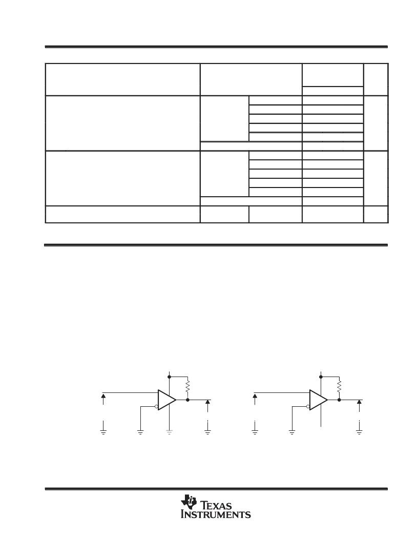
To verify that the input offset voltage falls within the limits specified, the limit value is applied to the input as shown
in Figure 1(a). With the noninverting input positive with respect to the inverting input, the output should be high. With
the input polarity reversed, the output should be low.
A similar test can be made to verify the input offset voltage at the common-mode extremes. The supply voltages can
be slewed as shown in Figure 1(b) for the V
ICR
test, rather than changing the input voltages, to provide greater
accuracy.
(a) VIO WITH VIC = 0 V
(b) VIO WITH VIC = 4 V
5 V
1 V
5.1 k
5.1 k
Applied VIO
Limit
Applied VIO
Limit
VO
VO
– 4 V
Figure 1. Method for Verifying That Input Offset Voltage Is Within Specified Limits
相關(guān)PDF資料 |
PDF描述 |
|---|---|
| TLC3545IDGKR | 5-V. LOW POWER, 14-BIT, 200-KSPS SERIAL ANALOG-TO-DIGITAL CONVERTERS WITH AUTO-POWER DOWN |
| TLC3545IDGKRG4 | 5-V. LOW POWER, 14-BIT, 200-KSPS SERIAL ANALOG-TO-DIGITAL CONVERTERS WITH AUTO-POWER DOWN |
| TLC372QP | LinCMOSE DUAL DIFFERENTIAL COMPARATORS |
| TLC372MFK | LinCMOSE DUAL DIFFERENTIAL COMPARATORS |
| TLC372Q | LinCMOSE DUAL DIFFERENTIAL COMPARATORS |
相關(guān)代理商/技術(shù)參數(shù) |
參數(shù)描述 |
|---|---|
| TLC34058 | 制造商:TI 制造商全稱:Texas Instruments 功能描述:256 ?? 24 COLOR PALETTE |
| TLC34058 WAF | 制造商:Texas Instruments 功能描述: |
| TLC34058-110FN | 制造商:TI 制造商全稱:Texas Instruments 功能描述:256 ?? 24 COLOR PALETTE |
| TLC34058-110FNR | 制造商:TI 制造商全稱:Texas Instruments 功能描述:256 ?? 24 COLOR PALETTE |
| TLC34058-110M | 制造商:TI 制造商全稱:Texas Instruments 功能描述:256 x 24 COLOR PALETTE |
發(fā)布緊急采購,3分鐘左右您將得到回復(fù)。