- 您現(xiàn)在的位置:買賣IC網(wǎng) > PDF目錄384002 > TL507l (Texas Instruments, Inc.) ANALOG-TO-DIGITAL CONVERTER PDF資料下載
參數(shù)資料
| 型號(hào): | TL507l |
| 廠商: | Texas Instruments, Inc. |
| 英文描述: | ANALOG-TO-DIGITAL CONVERTER |
| 中文描述: | 模擬到數(shù)字轉(zhuǎn)換器 |
| 文件頁(yè)數(shù): | 3/8頁(yè) |
| 文件大小: | 119K |
| 代理商: | TL507L |
TL507C, TL507l
ANALOG-TO-DIGITAL CONVERTER
SLAS041 – OCTOBER 1979 – REVISED OCTOBER 1988
3
POST OFFICE BOX 655303
DALLAS, TEXAS 75265
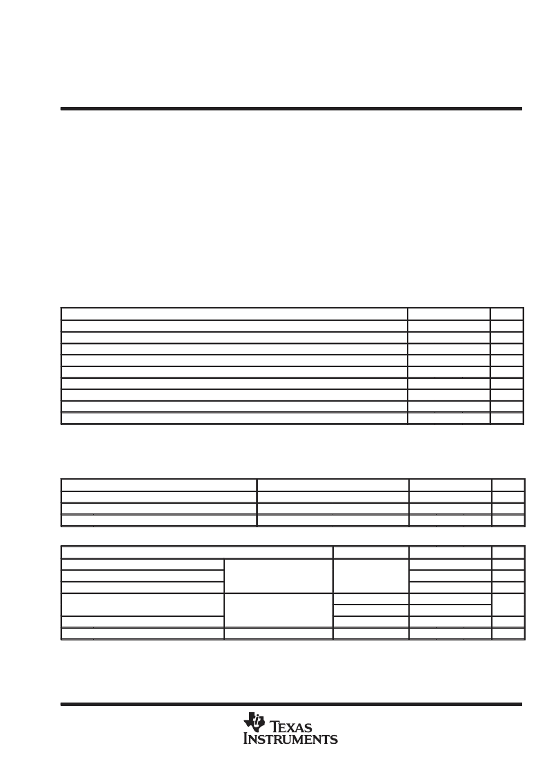
absolute maximum ratings over operating free-air temperature range (unless otherwise noted)
Supply voltage, V
CC1
(see Note 1)
Supply voltage, V
CC2
Input voltage at analog input
Input voltage at ENABLE, CLK, and RESET
On-state output voltage
Off-state output voltage
Continuous total dissipation at (or below) 25
°
C free-air temperature (see Note 2)
Operating free-air temperature range:TL507C
TL507I
Storage temperature range
. . . . . . . . . . . . . . . . . . . . . . . . . . . . . . . . . . . . . . . . . . . . . . . . . . . . . . .
Lead temperature 1,6 mm (1/16 inch) from case for 10 seconds
6.5 V
20 V
6.5 V
20 V
6 V
20 V
. . . . . . . . . . . . . . . . . . . . . . . . . . . . . . . . . . . . . . . . . . . . . . . . . . . . . . . . .
. . . . . . . . . . . . . . . . . . . . . . . . . . . . . . . . . . . . . . . . . . . . . . . . . . . . . . . . . . . . . . . . . . . . . .
. . . . . . . . . . . . . . . . . . . . . . . . . . . . . . . . . . . . . . . . . . . . . . . . . . . . . . . . . . . . . . .
. . . . . . . . . . . . . . . . . . . . . . . . . . . . . . . . . . . . . . . . . . . . . . . . . .
. . . . . . . . . . . . . . . . . . . . . . . . . . . . . . . . . . . . . . . . . . . . . . . . . . . . . . . . . . . . . . . . . . . . .
. . . . . . . . . . . . . . . . . . . . . . . . . . . . . . . . . . . . . . . . . . . . . . . . . . . . . . . . . . . . . . . . . . . .
1000 mW
0 to 70
°
C
. . . . . . . . . . . . .
. . . . . . . . . . . . . . . . . . . . . . . . . . . . . . . . . . . . . . . . . . . .
. . . . . . . . . . . . . . . . . . . . . . . . . . . . . . . . . . . . . . . .
–40
°
C to 85
°
C
–65
°
C to 150
°
C
260
°
C
. . . . . . . . . . . . . . . . . . . . . . . . . . . . . . .
NOTES:
1. Voltage values are with respect to network ground terminal unless otherwise noted.
2. For operation above 25
°
C free-air temperature, derate linearly to 520 mW at 85
°
C at the rate of 8.0 mW/
°
C.
recommended operating conditions
MIN
3.5
NOM
MAX
UNIT
V
V
V
V
V
V
V
V
kHz
Supply voltage, VCC1
Supply voltage, VCC2
Input voltage at ANALOG INPUT
Input voltage at ENABLE, CLK, and RESET
High-level input voltage, VIH, RESET and ENABLE
Low-level input voltage, VIL, RESET and ENABLE
On-state output voltage
Off-state output voltage
Clock frequency, fclock
5
6
8
0
15
18
5.5
±
18
2
0.8
5.5
1.8
150
0
125
electrical characteristics over recommended operating free-air temperature range,
V
CC1
= V
CC2
= 5 V (unless otherwise noted)
regular section
PARAMETER
TEST CONDITIONS
MIN
TYP
5.5
MAX
UNIT
V
mA
mA
VCC1
ICC1
ICC2
Supply voltage (output)
Supply current
Supply current
VCC2 = 10 V to 18 V,
VCC1 = 5 V,
VCC2 = 15 V,
ICC1 = 0 to –1 mA
VCC2 open
VCC1 open
5
6
8
5
7
10
inputs
PARAMETER
TEST CONDITIONS
MIN
TYP
MAX
4.5
UNIT
V
V
V
VT+
VT-
Vhys
Positive-going threshold voltage
Negative-going threshold voltage
Hysteresis (VT+ – VT–)
CLK
0.4
2
2.6
17
220
4
IIH
High level input current
High-level input current
VI = 2.4 V
VI = 18 V
VI = 0
VI = 4 V
35
320
±
10
300
A
μ
RESET, ENABLE, and CLK
130
IIL
II
All typical values are at TA = 25
°
C.
These parameters are linear functions of VCC1.
Low-level input current
Analog input current
μ
A
nA
10
相關(guān)PDF資料 |
PDF描述 |
|---|---|
| TL507C | ANALOG-TO-DIGITAL CONVERTER |
| TL750L05C | LOW-DROPOUT VOLTAGE REGULATORS |
| TL7702BMU | SUPPLY-VOLTAGE SUPERVISORS |
| TL7702BID | SUPPLY-VOLTAGE SUPERVISORS |
| TL7702BMFK | SUPPLY-VOLTAGE SUPERVISORS |
相關(guān)代理商/技術(shù)參數(shù) |
參數(shù)描述 |
|---|---|
| TL50AQ | 制造商:Banner Engineering 功能描述:Tower Light, 50mm, Audiable Alarm, 18-30VDC/24VAC, Black, QDC, 11374 |
| TL50B | 制造商:Banner Engineering 功能描述:TL50B TOWER LIGHT |
| TL50BA | 制造商:Banner Engineering 功能描述:TL50BA TOWER LIGHT |
| TL50BAQ | 制造商:Banner Engineering 功能描述:TL50BAQ TOWER LIGHT |
| TL50BBBBB | 制造商:Banner Engineering 功能描述:TL50BBBBB TOWER LIGHT |
發(fā)布緊急采購(gòu),3分鐘左右您將得到回復(fù)。