- 您現(xiàn)在的位置:買賣IC網(wǎng) > PDF目錄385927 > TL022M (Texas Instruments, Inc.) DUAL LOW-POWER OPERATIONAL AMPLIFIERS PDF資料下載
參數(shù)資料
| 型號: | TL022M |
| 廠商: | Texas Instruments, Inc. |
| 英文描述: | DUAL LOW-POWER OPERATIONAL AMPLIFIERS |
| 中文描述: | 雙低功耗運算放大器 |
| 文件頁數(shù): | 2/5頁 |
| 文件大小: | 87K |
| 代理商: | TL022M |

TL022C, TL022M
DUAL LOW-POWER OPERATIONAL AMPLIFIERS
SLOS076 – SEPTEMBER 1973 – REVISED SEPTEMBER 1990
2
POST OFFICE BOX 655303
DALLAS, TEXAS 75265
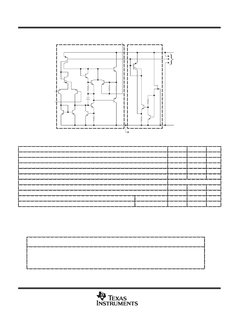
schematic
Each Amplifier
Common to Both
Amplifiers
VCC+
To Other
Amplifier
To Other Amplifier
VCC–
IN–
IN+
OUT
absolute maximum ratings over operating free-air temperature range (unless otherwise noted)
TL022C
TL022M
UNIT
Supply voltage, VCC+ (see Note 1)
Supply voltage, VCC– (see Note 1)
Differential input voltage (see Note 2)
18
22
V
–18
±
30
±
15
–22
±
30
±
15
V
V
Input voltage (any input, see Notes 1 and 3)
V
Duration of output short circuit (see Note 4)
unlimited
unlimited
Continuous total dissipation
See Dissipation Rating Table
Operating free-air temperature range
0 to 70
–55 to 125
°
C
°
C
°
C
°
C
Storage temperature range
–65 to 150
–65 to 150
Lead temperature 1,6 mm (1/16 inch) from case for 60 seconds
JG or U package
300
Lead temperature 1,6 mm (1/16 inch) from case for 10 seconds
D or P package
260
NOTES:
1. All voltage values, unless otherwise noted, are with respect to the midpoint between VCC+ and VCC–.
2. Differential voltages are at IN+ with respect to IN–.
3. The magnitude of the input voltage must never exceed the magnitude of the supply voltage or 15 V, whichever is less.
4. The output may be shorted to ground or either power supply. For the TL022M only, the unlimited duration of the short circuit applies
at (or below) 125
°
C case temperature or 75
°
C free-air temperature.
DISSIPATION RATING TABLE
PACKAGE
TA
≤
25
°
C
POWER RATING
DERATING
FACTOR
DERATE
ABOVE TA
33
°
C
69
°
C
65
°
C
25
°
C
TA = 70
°
C
POWER RATING
TA = 125
°
C
POWER RATING
D
680 mW
5.8 mW/
°
C
8.4 mW/
°
C
8.0 mW/
°
C
5.4 mW/
°
C
464 mW
—
JG
680 mW
672 mW
210 mW
P
680 mW
640 mW
—
U
675 mW
432 mW
135 mW
相關(guān)PDF資料 |
PDF描述 |
|---|---|
| TL022MJG | DUAL LOW-POWER OPERATIONAL AMPLIFIERS |
| TL022MU | DUAL LOW-POWER OPERATIONAL AMPLIFIERS |
| TL026C | DIFFERENTIAL HIGH-FREQUENCY AMPLIFIER WITH AGC |
| TL070CPW | JFET-INPUT OPERATIONAL AMPLIFIER |
| TL070D | JFET-INPUT OPERATIONAL AMPLIFIER |
相關(guān)代理商/技術(shù)參數(shù) |
參數(shù)描述 |
|---|---|
| TL022MJG | 制造商:TI 制造商全稱:Texas Instruments 功能描述:DUAL LOW-POWER OPERATIONAL AMPLIFIERS |
| TL022MU | 制造商:TI 制造商全稱:Texas Instruments 功能描述:DUAL LOW-POWER OPERATIONAL AMPLIFIERS |
| TL02366 | 制造商:Distributed By MCM 功能描述:12 Piece 3 Way Angled Screwdriver |
| TL02393 | 制造商:C&K Components 功能描述: |
| TL02441 | 制造商:PRO'S KIT 功能描述:HAND TOOL IDC |
發(fā)布緊急采購,3分鐘左右您將得到回復(fù)。