- 您現(xiàn)在的位置:買賣IC網(wǎng) > PDF目錄383999 > TISP4XXXH4BJ (Bourns Inc.) HIGH HOLDING CURRENT BIDIRECTIONAL THYRISTOR OVERVOLTAGE PROTECTORS PDF資料下載
參數(shù)資料
| 型號(hào): | TISP4XXXH4BJ |
| 廠商: | Bourns Inc. |
| 英文描述: | HIGH HOLDING CURRENT BIDIRECTIONAL THYRISTOR OVERVOLTAGE PROTECTORS |
| 中文描述: | 舉行高電流雙向可控硅過(guò)電壓保護(hù)器 |
| 文件頁(yè)數(shù): | 1/13頁(yè) |
| 文件大小: | 391K |
| 代理商: | TISP4XXXH4BJ |
當(dāng)前第1頁(yè)第2頁(yè)第3頁(yè)第4頁(yè)第5頁(yè)第6頁(yè)第7頁(yè)第8頁(yè)第9頁(yè)第10頁(yè)第11頁(yè)第12頁(yè)第13頁(yè)
NOVEMBER 1997 - REVISED FEBRUARY 2005
Specifications are subject to change without notice.
Customers should verify actual device performance in their specific applications.
TISP4xxxH4BJ Overvoltage Protector Series
TISP4165H4BJ THRU TISP4200H4BJ,
TISP4265H4BJ THRU TISP4350H4BJ
HIGH HOLDING CURRENT
BIDIRECTIONAL THYRISTOR OVERVOLTAGE PROTECTORS
T
R
SD4XAA
Terminals T and R correspond to the
alternative line designators of A and B
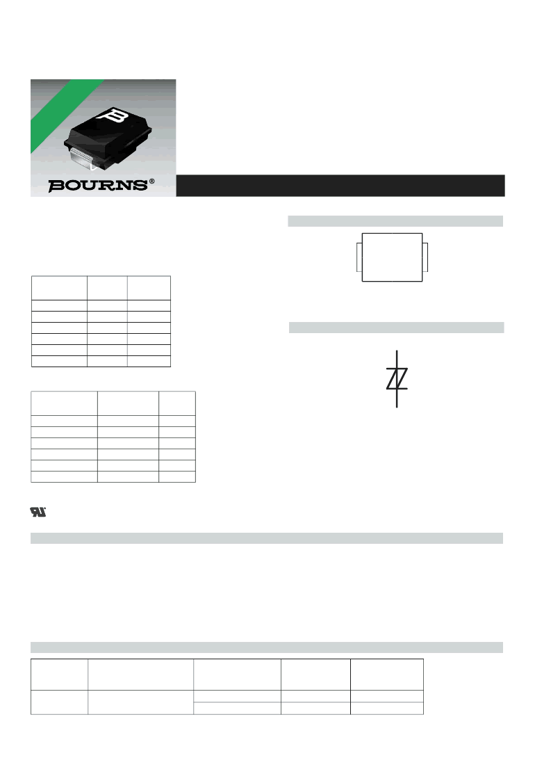
Device Symbol
Device
V
DRM
V
135
145
155
200
230
275
V
(BO)
V
165
180
200
265
300
350
‘4165
‘4180
‘4200
‘4265
‘4300
‘4350
Waveshape
Standard
I
TSP
A
500
300
250
200
160
100
2/10
μ
s
8/20
μ
s
10/160
μ
s
10/700
μ
s
10/560
μ
s
10/1000
μ
s
GR-1089-CORE
IEC 61000-4-5
FCC Part 68
ITU-T K.20/21
FCC Part 68
GR-1089-CORE
Rated for International Surge Wave Shapes
1
2
T(A)
R(B)
MDXXBG
How To Order
SMBJ Package (Top View)
Description
These devices are designed to limit overvoltages on the telephone line. Overvoltages are normally caused by a.c. power system or lightning
flash disturbances which are induced or conducted on to the telephone line. A single device provides 2-point protection and is typically used
for the protection of 2-wire telecommunication equipment (e.g., between the Ring and Tip wires for telephones and modems). Combinations of
devices can be used for multi-point protection (e.g., 3-point protection between Ring, Tip and Ground).
The protector consists of a symmetrical voltage-triggered bidirectional thyristor. Overvoltages are initially clipped by breakdown clamping until
the voltage rises to the breakover level, which causes the device to crowbar into a low-voltage on state. This low-voltage on state causes the
current resulting from the overvoltage to be safely diverted through the device. The high crowbar holding current prevents d.c. latchup as the
diverted current subsides.
ITU-T K.20/21 Rating .......................8 kV 10/700, 200 A 5/310
High Holding Current ........................................... 225 mA min.
Ion-Implanted Breakdown Region
Precise and Stable Voltage
Low Voltage Overshoot under Surge
Low Differential Capacitance ................................. 67 pF max.
.............................................. UL Recognized Component
*RoHS Directive 2002/95/EC Jan 27 2003 including Annex
Device
Package
Carrier
TISP4xxxH4BJ
BJ (J-Bend DO-214AA/SMB)
Embossed Tape Reeled
Bulk Pack
TISP4xxxH4BJR
TISP4xxxH4BJ
TISP4xxxH4BJR-S
TISP4xxxH4BJ-S
Insert xxx value corresponding to protection voltages of 165 through to 350.
For Standard
Termination Finish
Order As
For Lead Free
Termination Finish
Order As
*RHAVALABE
VRSONS
相關(guān)PDF資料 |
PDF描述 |
|---|---|
| TISP4XXXJ1BJ | BIDIRECTIONAL THYRISTOR OVERVOLTAGE PROTECTORS |
| TISP4XXXL3BJ | BIDIRECTIONAL THYRISTOR OVERVOLTAGE PROTECTORS |
| TISP4XXXL3LM | BIDIRECTIONAL THYRISTOR OVERVOLTAGE PROTECTORS |
| TISP61089AD | DUAL FORWARD-CONDUCTING P-GATE THYRISTORS PROGRAMMABLE OVERVOLTAGE PROTECTORS |
| TISP61089ASD | DUAL FORWARD-CONDUCTING P-GATE THYRISTORS PROGRAMMABLE OVERVOLTAGE PROTECTORS |
相關(guān)代理商/技術(shù)參數(shù) |
參數(shù)描述 |
|---|---|
| TISP4XXXJ1BJ | 制造商:BOURNS 制造商全稱:Bourns Electronic Solutions 功能描述:BIDIRECTIONAL THYRISTOR OVERVOLTAGE PROTECTORS |
| TISP4XXXJ3BJ | 制造商:BOURNS 制造商全稱:Bourns Electronic Solutions 功能描述:BIDIRECTIONAL THYRISTOR OVERVOLTAGE PROTECTORS |
| TISP4XXXL3AJ | 制造商:BOURNS 制造商全稱:Bourns Electronic Solutions 功能描述:BIDIRECTIONAL THYRISTOR OVERVOLTAGE PROTECTORS |
| TISP4XXXL3BJ | 制造商:BOURNS 制造商全稱:Bourns Electronic Solutions 功能描述:BIDIRECTIONAL THYRISTOR OVERVOLTAGE PROTECTORS |
| TISP4XXXL3LM | 制造商:BOURNS 制造商全稱:Bourns Electronic Solutions 功能描述:BIDIRECTIONAL THYRISTOR OVERVOLTAGE PROTECTORS |
發(fā)布緊急采購(gòu),3分鐘左右您將得到回復(fù)。