- 您現(xiàn)在的位置:買賣IC網(wǎng) > PDF目錄98226 > THS4271DGKG4 (TEXAS INSTRUMENTS INC) 1 CHANNEL, VIDEO PREAMPLIFIER, PDSO8 PDF資料下載
參數(shù)資料
| 型號: | THS4271DGKG4 |
| 廠商: | TEXAS INSTRUMENTS INC |
| 元件分類: | 音頻/視頻放大 |
| 英文描述: | 1 CHANNEL, VIDEO PREAMPLIFIER, PDSO8 |
| 封裝: | GREEN, PLASTIC, MSOP-8 |
| 文件頁數(shù): | 19/48頁 |
| 文件大?。?/td> | 1227K |
| 代理商: | THS4271DGKG4 |
第1頁第2頁第3頁第4頁第5頁第6頁第7頁第8頁第9頁第10頁第11頁第12頁第13頁第14頁第15頁第16頁第17頁第18頁當(dāng)前第19頁第20頁第21頁第22頁第23頁第24頁第25頁第26頁第27頁第28頁第29頁第30頁第31頁第32頁第33頁第34頁第35頁第36頁第37頁第38頁第39頁第40頁第41頁第42頁第43頁第44頁第45頁第46頁第47頁第48頁

IMD3 = PS - PO
PS
PO
fc = fc - f1
fc = f2 - fc
PS
fc - 3f
f1 fc f2
fc + 3f
Power
f - Frequency - MHz
OIP
3
+ PO )
IMD
3
2
where
P
O
+ 10 log
V2
P
2R
L
0.001
IMD3
OIP3
IIP3
3X
PIN
(dBm)
1X
POUT
(dBm)
PO
PS
SLOS397F – JULY 2002 – REVISED OCTOBER 2009
www.ti.com
Intercept points are specifications long used as key
Due to the intercept point ease of use in system level
design criteria in the RF communications world as a
calculations for receiver chains, it has become the
metric for the intermodulation distortion performance
specification of choice for guiding distortion-related
of a device in the signal chain (e.g., amplifiers,
design decisions. Traditionally, these systems use
mixers, etc.). Use of the intercept point, rather than
primarily class-A, single-ended RF amplifiers as gain
strictly the intermodulation distortion, allows simpler
blocks. These RF amplifiers are typically designed to
system-level calculations. Intercept points, like noise
operate in a 50-
environment. Giving intercept
figures, can be easily cascaded back and forth
points in dBm, implies an associated impedance (50
through a signal chain to determine the overall
).
receiver chain intermodulation distortion performance.
However, with an operational amplifier, the output
The relationship between intermodulation distortion
does not require termination as an RF amplifier
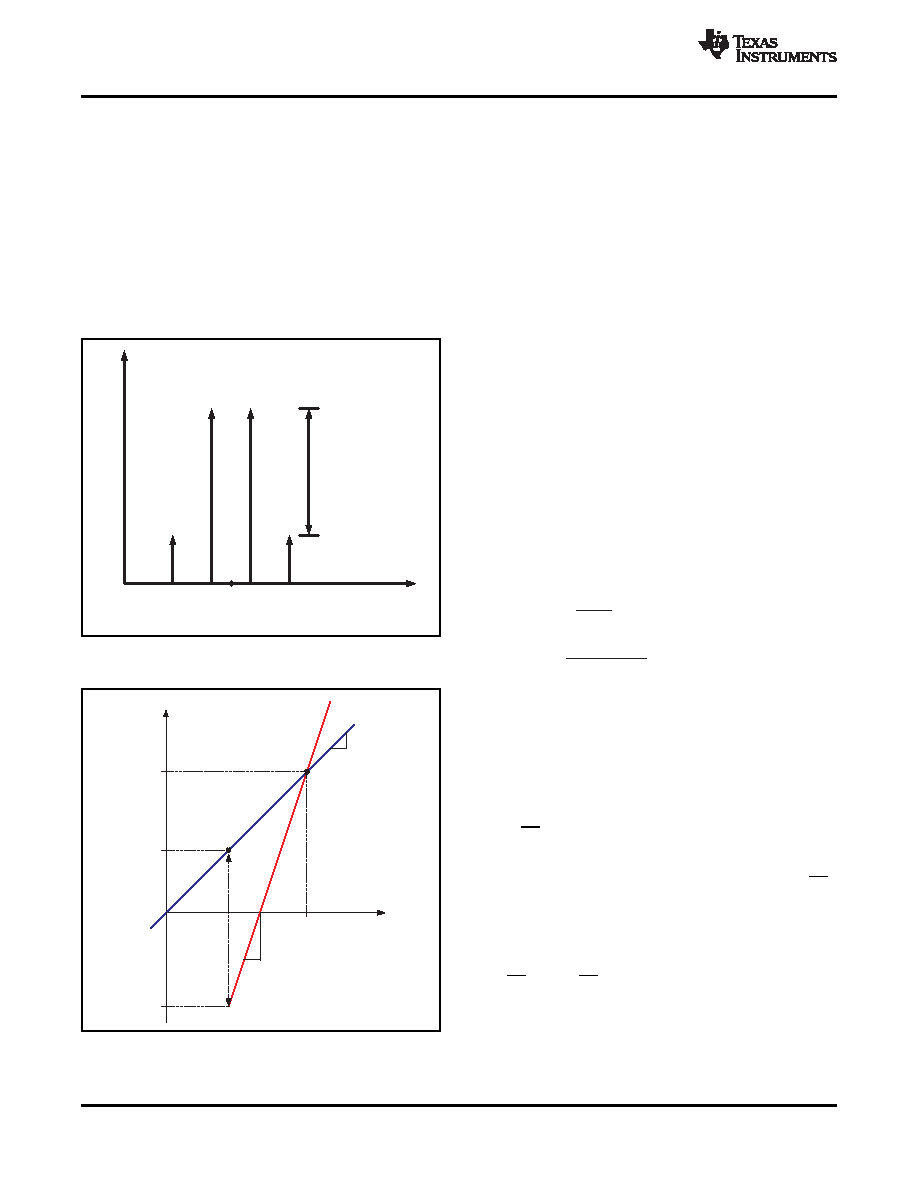
and intercept point is depicted in Figure 85 and
would. Because closed-loop amplifiers deliver signals
to their outputs regardless of the impedance present,
it is important to comprehend this when evaluating
the intercept point of an operational amplifier. The
THS4271 yields optimum distortion performance
when loaded with 150
to 1 k, very similar to the
input impedance of an analog-to-digital converter
over its input frequency band.
As a result, terminating the input of the ADC to 50
can actually be detrimental to systems performance.
The
discontinuity
between
open-loop,
class-A
amplifiers
and
closed-loop,
class-AB
amplifiers
becomes apparent when comparing the intercept
points of the two types of devices. Equation 2 and
Equation 3 give the definition of an intercept point,
relative to the intermodulation distortion.
(2)
Figure 85.
(3)
NOTE: PO is the output power of a single tone, RL
is the load resistance, and VP is the peak
voltage for a single tone.
NOISE ANALYSIS
High slew rate, unity gain stable, voltage-feedback
operational amplifiers usually achieve the slew rate at
the expense of a higher input noise voltage. The
3-nV/
√Hz input voltage noise for the THS4271 and
THS4275 is, however, much lower than comparable
amplifiers. The input-referred voltage noise, and the
two input-referred current noise terms (3 pA/
√Hz),
combine to give low output noise under a wide variety
of operating conditions. Figure 87 shows the amplifier
noise analysis model with all the noise terms
included. In this model, all noise terms are taken to
be noise voltage or current density terms in either
nV/
√Hz or pA/√Hz.
Figure 86.
26
Copyright 2002–2009, Texas Instruments Incorporated
相關(guān)PDF資料 |
PDF描述 |
|---|---|
| THS4271DGNG4 | 1 CHANNEL, VIDEO PREAMPLIFIER, PDSO8 |
| THS4271DRBRG4 | 1 CHANNEL, VIDEO PREAMPLIFIER, PDSO8 |
| THS4271DRBTG4 | 1 CHANNEL, VIDEO PREAMPLIFIER, PDSO8 |
| THS4271DRG4 | 1 CHANNEL, VIDEO PREAMPLIFIER, PDSO8 |
| THS4271DGNR | 1 CHANNEL, VIDEO AMPLIFIER, PDSO8 |
相關(guān)代理商/技術(shù)參數(shù) |
參數(shù)描述 |
|---|---|
| THS4271DGKR | 功能描述:高速運算放大器 Super-Fast Ultra-Low Distortion RoHS:否 制造商:Texas Instruments 通道數(shù)量:1 電壓增益 dB:116 dB 輸入補償電壓:0.5 mV 轉(zhuǎn)換速度:55 V/us 工作電源電壓:36 V 電源電流:7.5 mA 最大工作溫度:+ 85 C 安裝風(fēng)格:SMD/SMT 封裝 / 箱體:SOIC-8 封裝:Tube |
| THS4271DGKRG4 | 功能描述:高速運算放大器 Super-Fast Ultra-Low Distortion RoHS:否 制造商:Texas Instruments 通道數(shù)量:1 電壓增益 dB:116 dB 輸入補償電壓:0.5 mV 轉(zhuǎn)換速度:55 V/us 工作電源電壓:36 V 電源電流:7.5 mA 最大工作溫度:+ 85 C 安裝風(fēng)格:SMD/SMT 封裝 / 箱體:SOIC-8 封裝:Tube |
| THS4271DGN | 功能描述:高速運算放大器 Super-Fast Ultra-Low Distortion RoHS:否 制造商:Texas Instruments 通道數(shù)量:1 電壓增益 dB:116 dB 輸入補償電壓:0.5 mV 轉(zhuǎn)換速度:55 V/us 工作電源電壓:36 V 電源電流:7.5 mA 最大工作溫度:+ 85 C 安裝風(fēng)格:SMD/SMT 封裝 / 箱體:SOIC-8 封裝:Tube |
| THS4271DGN | 制造商:Texas Instruments 功能描述:IC SM OP-AMP HI-SPEED VFB |
| THS4271DGN | 制造商:Texas Instruments 功能描述:OP AMP HIGH SPEED VFB HTSSOP 427 |
發(fā)布緊急采購,3分鐘左右您將得到回復(fù)。