- 您現(xiàn)在的位置:買賣IC網(wǎng) > PDF目錄383995 > TEA1093T (NXP SEMICONDUCTORS) Hands-free IC PDF資料下載
參數(shù)資料
| 型號: | TEA1093T |
| 廠商: | NXP SEMICONDUCTORS |
| 元件分類: | 通信及網(wǎng)絡 |
| 英文描述: | Hands-free IC |
| 中文描述: | SPECIALTY TELECOM CIRCUIT, PDSO28 |
| 封裝: | 7.50 MM, PLASTIC, SOT-136-1, MS-013AE, SO-28 |
| 文件頁數(shù): | 12/28頁 |
| 文件大?。?/td> | 208K |
| 代理商: | TEA1093T |
第1頁第2頁第3頁第4頁第5頁第6頁第7頁第8頁第9頁第10頁第11頁當前第12頁第13頁第14頁第15頁第16頁第17頁第18頁第19頁第20頁第21頁第22頁第23頁第24頁第25頁第26頁第27頁第28頁
1996 Feb 09
12
Philips Semiconductors
Product specification
Hands-free IC
TEA1093
To determine the noise level, the signal on TENV and
RENV are buffered to TNOI and RNOI. These buffers have
a maximum source current of 1
μ
A and a maximum sink
current of 120
μ
A. Together with the capacitors C
TNOI
and
C
RNOI
, the timing can be set. In the basic application of
Fig.16, the value of both capacitors is 4.7
μ
F. At room
temperature, the 1
μ
A sourced current corresponds to a
maximum rise-slope of the noise envelope of
approximately 0.07 dB/ms. This is small enough to track
background noise and not to be influenced by speech
bursts. The 120
μ
A current that is sunk corresponds to a
maximum fall-slope of approximately 8.5 dB/ms. However,
during the decrease of the signal envelope, the noise
envelope tracks the signal envelope so it will never fall
faster than approximately 0.7 dB/ms. The behaviour of the
signal envelope and noise envelope monitors is
illustrated in Fig.9.
D
ECISION LOGIC
:
PINS
IDT
AND
SWT
The TEA1093 selects its mode of operation (transmit,
receive or idle mode) by comparing the signal and the
noise envelopes of both channels. This is executed by the
decision logic. The resulting voltage on pin SWT is the
input for the voice-switch.
To facilitate the distinction between signal and noise, the
signal is considered as speech when its envelope is more
than 4.3 dB above the noise envelope. At room
temperature, this is equal to a voltage difference
V
ENV
V
NOI
= 13 mV. This so called speech/noise
threshold is implemented in both channels.
The signal on MIC contains both speech and the signal
coming from the loudspeaker (acoustic coupling). When
receiving, the contribution from the loudspeaker overrules
the speech. As a result, the signal envelope on TENV is
formed mainly by the loudspeaker signal. To correct this,
an attenuator is connected between TENV and the
TENV/RENV comparator. Its attenuation equals that
applied to the microphone amplifier.
When a dial tone is present on the line, without monitoring,
the tone would be recognized as noise because it is a
signal with a constant amplitude. This would cause the
TEA1093 to go into the idle mode and the user of the set
would hear the dial tone fade away. To prevent this, a dial
tone detector is incorporated which, in standard
applications, does not consider input signals between
RIN1 and RIN2 as noise when they have a level greater
than 127 mV (RMS). This level is proportional to R
RSEN
.
As can be seen from Fig.10, the output of the decision
logic is a current source. The logic table gives the
relationship between the inputs and the value of the
current source. It can charge or discharge the capacitor
C
SWT
with a current of 10
μ
A (switch-over). If the current is
zero, the voltage on SWT becomes equal to the voltage on
IDT via the high-ohmic resistor R
IDT
(idling). The resulting
voltage difference between SWT and IDT determines the
mode of the TEA1093 and can vary between
400 mV
and +400 mV.
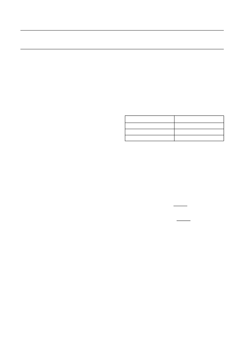
Table 1
Modes of TEA1093
The switch-over timing can be set with C
SWT
, the idle mode
timing with C
SWT
and R
IDT
. In the basic application given in
Fig.16, C
SWT
is 220 nF and R
IDT
is 2.2 M
. This enables a
switch-over time from transmit to receive mode or
vice-versa of approximately 13 ms (580 mV swing on
SWT). The switch-over time from idle mode to transmit
mode or receive mode is approximately 4 ms (180 mV
swing on SWT).
The switch over, from receive mode or transmit mode to
idle mode, is equal to 4
×
R
IDT
×
C
SWT
and is
approximately 2 seconds (idle mode time).
The inputs MUTET and DLC/MUTER overrule the decision
logic. When MUTET goes HIGH, the capacitor C
SWT
is
charged with 10
μ
A thus resulting in the receive mode.
When the voltage on pin DLC/MUTER goes lower than
0.2 V, the capacitor is discharged with 10
μ
A thus resulting
in the transmit mode.
V
OICE
-
SWITCH
:
PINS
STAB
AND
SWR
A diagram of the voice-switch is illustrated in Fig.11. With
the voltage on SWT, the TEA1093 voice-switch regulates
the gains of the transmit and the receive channel so that
the sum of both is kept constant.
V
SWT
V
IDT
(mV)
<
180
0
>+180
MODE
transmit mode
idle mode
receive mode
相關PDF資料 |
PDF描述 |
|---|---|
| TEA1094 | Hands free IC |
| TEA1094A | Hands free IC |
| TEA1094AM | Hands free IC |
| TEA1094AT | Hands free IC |
| TEA1094T | Hands free IC |
相關代理商/技術參數(shù) |
參數(shù)描述 |
|---|---|
| TEA1094 | 制造商:PHILIPS 制造商全稱:NXP Semiconductors 功能描述:Hands free IC |
| TEA1094A | 制造商:PHILIPS 制造商全稱:NXP Semiconductors 功能描述:Hands free IC |
| TEA1094AM | 制造商:PHILIPS 制造商全稱:NXP Semiconductors 功能描述:Hands free IC |
| TEA1094AT | 制造商:PHILIPS 制造商全稱:NXP Semiconductors 功能描述:Hands free IC |
| TEA1094T | 制造商:PHILIPS 制造商全稱:NXP Semiconductors 功能描述:Hands free IC |
發(fā)布緊急采購,3分鐘左右您將得到回復。