- 您現(xiàn)在的位置:買賣IC網 > PDF目錄385912 > TC90A66F (Toshiba Corporation) PAP/PIP/POP Controller for Wide-Screen TVs (PAL/NTSC) PDF資料下載
參數資料
| 型號: | TC90A66F |
| 廠商: | Toshiba Corporation |
| 英文描述: | PAP/PIP/POP Controller for Wide-Screen TVs (PAL/NTSC) |
| 中文描述: | 人民行動黨/畫中畫/持久性有機污染物控制的寬屏幕電視(PAL / NTSC制式) |
| 文件頁數: | 9/39頁 |
| 文件大?。?/td> | 488K |
| 代理商: | TC90A66F |
第1頁第2頁第3頁第4頁第5頁第6頁第7頁第8頁當前第9頁第10頁第11頁第12頁第13頁第14頁第15頁第16頁第17頁第18頁第19頁第20頁第21頁第22頁第23頁第24頁第25頁第26頁第27頁第28頁第29頁第30頁第31頁第32頁第33頁第34頁第35頁第36頁第37頁第38頁第39頁
TC90A66F
2001-06-07
9
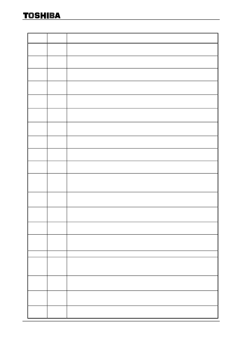
Pin Description
Pin Number Pin Name
Function
2
YINS
Y-signal (S system) analog input
Input amplitude is 1 V
p-p
typical.
4
IINS
I or R-Y signal (S system) analog input
Input amplitude is 1 V
p-p
typical.
6
QINS
Q or B-Y signal (S system) analog input
Input amplitude is 1 V
p-p
typical.
8
VRTY
High-level reference power supply pin for ADC Y signal. Sets the upper limit of the ADC dynamic
range. Fixed to 2.2 V (typ.) by internal resistance type potential division. Connect 0.1
μ
F bypass
capacitor between the pin and GND.
9
VRBY
Low-level reference power supply voltage for ADC Y signal. Sets the lower limit of the ADC dynamic
range. Fixed to 1.1 V (typ.) by internal resistance type potential division. Connect 0.1
μ
F bypass
capacitor between the pin and GND.
10
VRTC
High-level reference power supply pin for ADC IQ signal. Sets the upper limit of the ADC dynamic
range. Fixed to 2.2 V (typ.) by internal resistance type potential division. Connect 0.1
μ
F bypass
capacitor between the pin and GND.
11
VRBC
Low-level reference power supply voltage for ADC IQ signal. Sets the lower limit of the ADC dynamic
range. Fixed to 1.1 V (typ.) by internal resistance type potential division. Connect 0.1
μ
F bypass
capacitor between the pin and GND.
13
YINE
Y signal (E system) analog input
Input amplitude is 1 V
p-p
typical.
15
IINE
I or R-Y signal (E system) analog input
Input amplitude is 1 V
p-p
typical.
17
QINE
Q or B-Y signal (E system) analog input
Input amplitude is 1 V
p-p
typical.
23
CLAMP
Clamp signal monitor output pin.
Can monitor clamp pulse start/stop position set at 24h or 25h.
Outputs signal for the last data (S or E system) transfer.
34
WVDE
(E system) vertical sync signal input pin. (It can be inverted using I
2
C bus)
Inputs vertical sync signal from VCD for sub picture E. It is composing 5 V interface. For negative
polarity input, set sub address [26H: EVINV] to L (negative polarity input).
(E system) horizontal sync signal input pin. (It can be inverted using I
2
C bus)
Inputs horizontal sync signal from VCD for sub picture E. It is composing 5 V interface. For negative
polarity input, set sub address [26H: EHINV] to L (negative polarity input).
(E system) write clock input pin. Inputs from the external PLL circuit. It is composing 5 V interface.
35
WHDE
37
WCKE
Inputs 2400 fH for both 4M and 2M memory mode.
38
WHREFE
(E system) PLL phase comparison output.
The HREF signal obtained by the I/N divider circuit or the phase comparison result of sub picture (E)
horizontal sync signal.
40
HRST
Unit adjustment (WS/WE/R switch able)
41
MOH
External field memory use signal output pin.
Output amplitude is 3.3 V
p-p
typical.
Setting sub address [21H: MOH] to H uses TC90A66F; setting to L sets all memory output pins to Hi-Z.
42
WVDS
(S system) vertical sync signal input pin. (It can be inverted using I
2
C bus)
Inputs vertical sync signal from VCD for sub picture S. It is composing 5 V interface. For negative
polarity input, set sub address [27H: WVINV] to L (negative polarity input).
(S system) horizontal sync signal input pin. (It can be inverted using I
2
C bus)
Inputs horizontal sync signal from VCD for sub picture S. It is composing 5 V interface. For negative
polarity input, set sub address [27H: WHINV] to L (negative polarity input).
(S system) write clock input pin. Inputs from the external PLL circuit. It is composing 5 V interface.
43
WHDS
45
WCKS
Inputs 2400 fH for both 4M and 2M memory mode.
相關PDF資料 |
PDF描述 |
|---|---|
| TC9155AP | The TC9155/56AP is an optimum C2MOS IC which has been designed for electronization of tone control of audio equipment with the following features |
| TC9156AP | The TC9155/56AP is an optimum C2MOS IC which has been designed for electronization of tone control of audio equipment with the following features |
| TC9172AP | HIGH SPEED PLL WITH BUILT-IN PRESCALER |
| TC9227AP | HIGH SPEED PLL WITH BUILT-IN PRESCALER |
| TC9227P | HIGH SPEED PLL WITH BUILT-IN PRESCALER |
相關代理商/技術參數 |
參數描述 |
|---|---|
| TC90A67F | 制造商:TOSHIBA 制造商全稱:Toshiba Semiconductor 功能描述:TOSHIBA CMOS Digital Integrated Circuit Silicon Monolithic |
| TC90A69FG(ELP) | 功能描述:視頻 IC Multi Color 3Line Comb RoHS:否 制造商:Fairchild Semiconductor 工作電源電壓:5 V 電源電流:80 mA 最大工作溫度:+ 85 C 封裝 / 箱體:TSSOP-28 封裝:Reel |
| TC90A69NG | 功能描述:視頻 IC Multi Color 3Line Comb RoHS:否 制造商:Fairchild Semiconductor 工作電源電壓:5 V 電源電流:80 mA 最大工作溫度:+ 85 C 封裝 / 箱體:TSSOP-28 封裝:Reel |
| TC90A80F | 制造商:TOSHIBA 制造商全稱:Toshiba Semiconductor 功能描述:3-Line Digital Comb Filter for VCR, YNR/CNR, and Skew Correctors (NTSC) |
| TC90A80N | 制造商:TOSHIBA 制造商全稱:Toshiba Semiconductor 功能描述:3-Line Digital Comb Filter for VCR, YNR/CNR, and Skew Correctors (NTSC) |
發(fā)布緊急采購,3分鐘左右您將得到回復。