- 您現(xiàn)在的位置:買賣IC網(wǎng) > PDF目錄297490 > T5323-1M (VALPEY FISHER CORP) CRYSTAL OSCILLATOR, CLOCK, 1 MHz, HCMOS OUTPUT PDF資料下載
參數(shù)資料
| 型號(hào): | T5323-1M |
| 廠商: | VALPEY FISHER CORP |
| 元件分類: | XO, clock |
| 英文描述: | CRYSTAL OSCILLATOR, CLOCK, 1 MHz, HCMOS OUTPUT |
| 封裝: | ROHS COMPLIANT, HERMETIC SEALED, CERAMIC, SMD, LCC-4 |
| 文件頁(yè)數(shù): | 2/6頁(yè) |
| 文件大小: | 250K |
| 代理商: | T5323-1M |
75 South Street, Hopkinton, MA 01748 800-982-5737 508-435-6831 FAX 508-435-5289 www.valpeyfisher.com RevE0910
2
T5321 Series
T5421 Series
5 x 7 mm Surface Mount High Reliability
Tristate/Non-Tristate, 1MHz to 100MHz
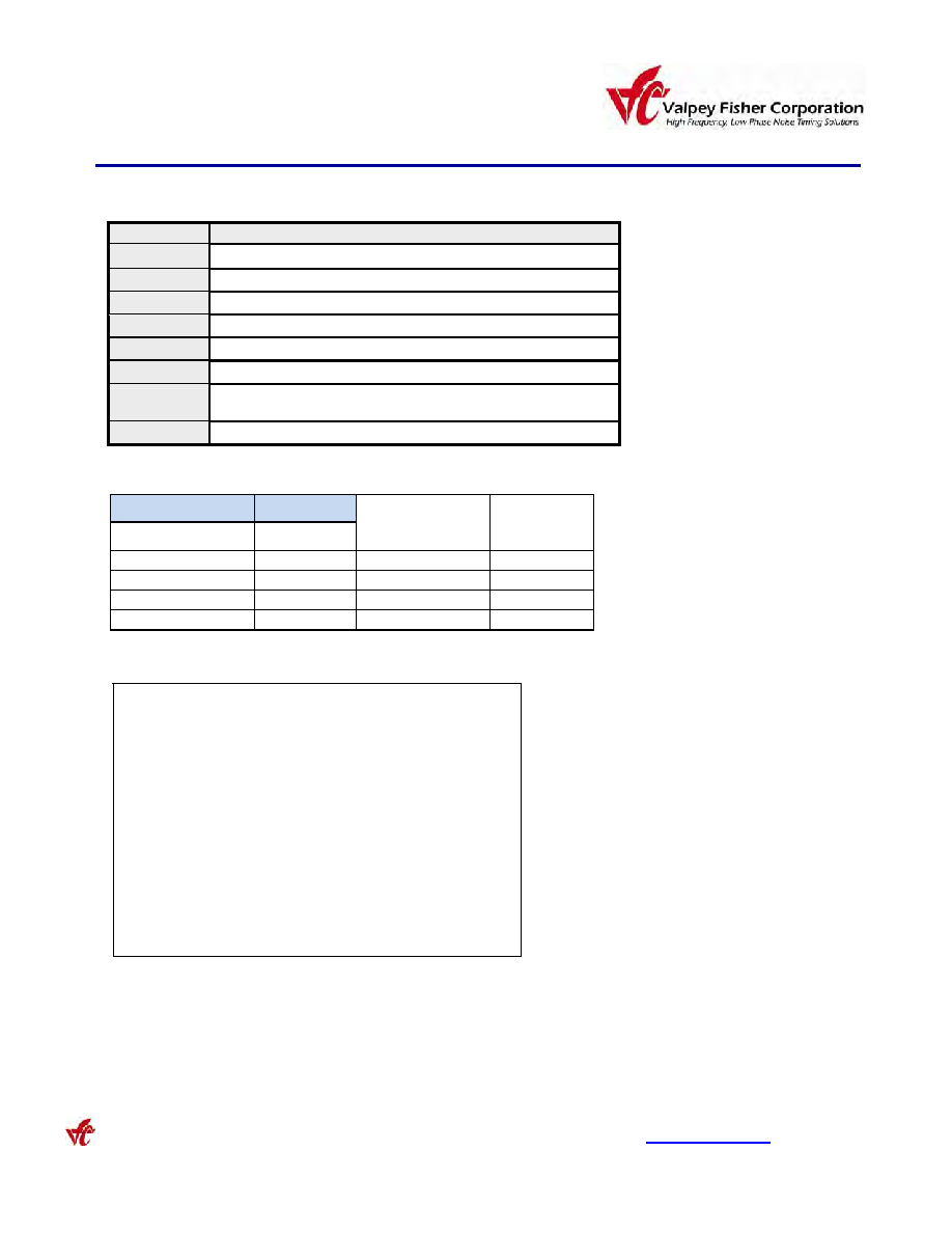
Parameter
Condition
Shock
1000 Gs, 0.35 ms, sine wave, 3 shocks in each plane
Vibration
10-2000 Hz of .06” d.a. or 20Gs, whichever is less
Humidity
Resistant to 85° R.H. at 85°C
Leak
Per MIL-STD-883, Method 1014, Cond. A1 and C1
Case
Hermetically sealed ceramic LCC
Pads
40 microinch of gold over nickel
Resistance
to Solvents
Per MIL-STD-202, Method 215
Marking
Epoxy ink or laser engraved
FIXED OUTPUT
TRISTATE
Operating
Temperature
Frequency
Stability
Model
T5321
T5421
-55
C to +85C
±25 ppm
T5322
T5422
-55
C to +85C
±50 ppm
T5323
T5423
-55
C to +125C
±75 ppm
T5324
T5424
-55
C to +125C
±50 ppm
Environmental and Mechanical Conditions
Thermal Characteristics
Thermal Resistance
From Junction to Case, Rjc
16 °C/Watt
Surface Mount Application
These packages are designed for reflow soldering
in accordance with recommended profiles. For
hand-soldering, the temperature of the iron should
not exceed 400°C for three seconds.
Table 1
Each unit undergoes the following:
1. Stabilization Bake
MIL-STD-883 Method 1008, Cond,.B
2. Temperature Cycling
MIL-STD-883 Method 1010, Cond, B
3. Constant Acceleration
MIL-STD-883 Method 2001, Cond, A
4. Burn-in
MIL-STD-883 Method 1015, Cond B
(125°C for 168 hours with bias)
5. Fine Leak
MIL-STD-883 Method 1014, Cond. A1
6. Gross Leak
MIL-STD-883 Method 1014, Cond C
7. Electrical Test at 25°C and temperature extremes, as follows:
A. Frequency
F. Duty Cycle
B. Current
G. Frequency at 3.65V
C. Rise Time
H. Frequency at 3.0V
D. Fall Time
I. “Zero” logic level
E. Duty Cycle
J. “One” logic level
K. Tristate
Test Data on each unit is available for additional cost
相關(guān)PDF資料 |
PDF描述 |
|---|---|
| T5623-32M | CRYSTAL OSCILLATOR, CLOCK, 32 MHz, HCMOS OUTPUT |
| T5724-40M | CRYSTAL OSCILLATOR, CLOCK, 40 MHz, HCMOS OUTPUT |
| T630 | Radiation hard 16-Bit ParallelError Detection & Correction |
| T6A6CI | Bi-Directional Triode Thyristor 6A Mold TRIAC |
| T70HFL10S10 | 70 A, 100 V, SILICON, RECTIFIER DIODE |
相關(guān)代理商/技術(shù)參數(shù) |
參數(shù)描述 |
|---|---|
| T532N | 制造商:Apex Tool Group 功能描述:CUTTER 5" DIAG MED OVAL HD SUP |
| T5331 | 制造商:TE Connectivity 功能描述: |
| T5333 | 制造商:未知廠家 制造商全稱:未知廠家 功能描述:TRIANGULAR TYPE |
| T5337 | 制造商:TE Connectivity 功能描述: |
| T5338 | 制造商:TE Connectivity 功能描述: |
發(fā)布緊急采購(gòu),3分鐘左右您將得到回復(fù)。