- 您現(xiàn)在的位置:買賣IC網(wǎng) > PDF目錄383874 > T40HFL60S02 (International Rectifier) DC/DC 5V:5V+5V 1W DBL ISO SIP7 RoHS Compliant: Yes PDF資料下載
參數(shù)資料
| 型號: | T40HFL60S02 |
| 廠商: | International Rectifier |
| 英文描述: | DC/DC 5V:5V+5V 1W DBL ISO SIP7 RoHS Compliant: Yes |
| 中文描述: | 快速恢復(fù)二極管 |
| 文件頁數(shù): | 3/13頁 |
| 文件大小: | 219K |
| 代理商: | T40HFL60S02 |
3
www.irf.com
T..HFL Series
Bulletin I27107 rev. A 09/97
T
J
T
stg
R
thJC
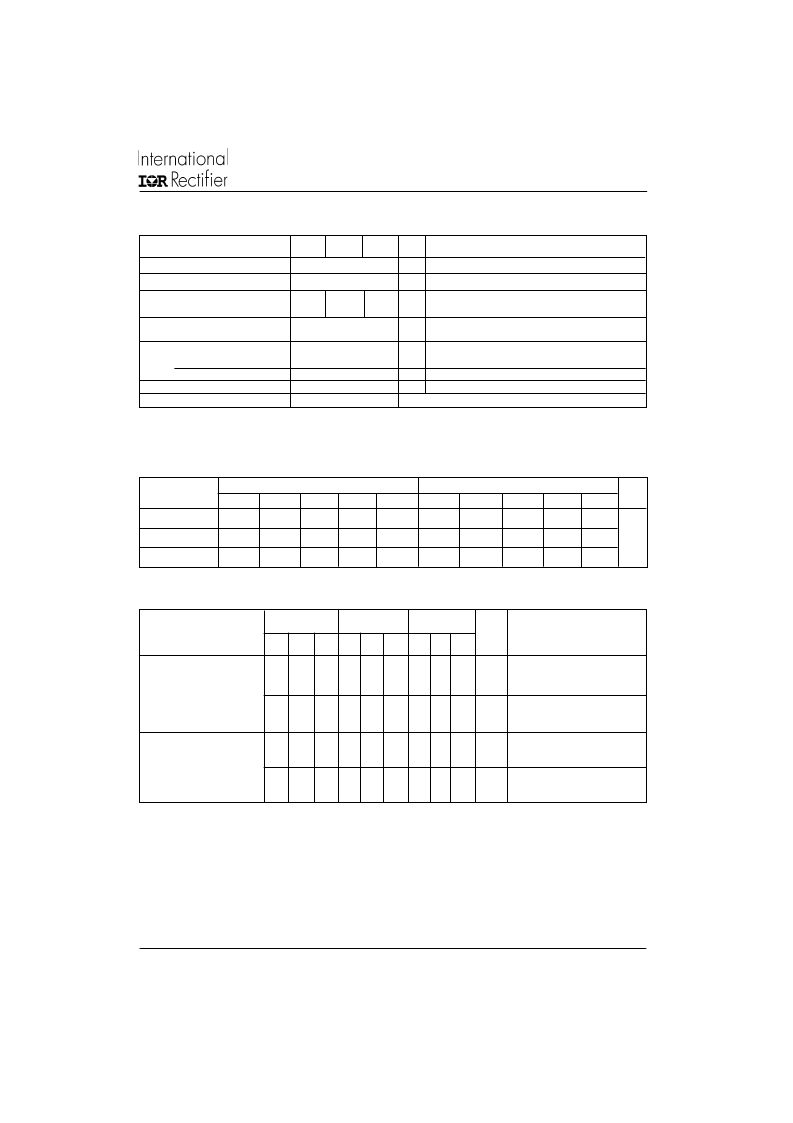
Junction operating temp.
Storage temperature range
-40 to 125
-40 to 150
o
C
o
C
Max. internal thermal
resistance junction to case
R
thC-S
Thermal resistance, case
to heatsink
T
Mounting
torque ±10% heatsink
Busbar to Terminal
wt
Approximate weight
Case style
(2)
A mounting compound is recommended and the torque should be rechecked after a period of about 3 hours to allow for the
spread of the compound
Mounting surface flat, smooth and greased.
Per module
M3.5 mounting screws
(2)
Non-lubricated threads
M5 screws terminals; non-lubricated threads
g (oz) See outline table
T-MODULE
Base to
1.3 ±10%
Nm
3 ±10%
54 (19)
D-56
Nm
(*) Tested on LEM 300A Diodemeter Tester
0.2
K/W
Thermal and Mechanical Specifications
0.85
0.53
0.46
K/W Per module, DC operation
T40HFL
T70HFL
T85HFL
Parameter
Units
Conditions (*)
S02 S05 S10 S02 S05 S10 S02 S05 S10
t
rr
Maximum reverse
recovery time
T
J
= 25 °C, -di
F
/dt = 100A/
μ
s
I
F
= 1 A to V
R
= 30V
T
J
= 25 °C, -di
F
/dt = 25A/
μ
s
I
FM
=
π
x rated I
F(AV),
V
R
= -30 V
Q
rr
Maximum reverse
recovered charge
T
J
= 25 °C, -di
F
/dt = 100A/
μ
s
I
F
= 1 A to V
R
= 30V
T
J
= 25 °C, -di
F
/dt = 25A/
μ
s
I
FM
=
π
x rated I
F(AV)
V
R
= -30 V
200
500 1000 200 500 1000 200 500 1000
ns
0.25
0.4
1.35 0.25 0.4 1.35 0.3
0.6
1.6
μ
C
0.55
2.0
8.0
0.6
2.1
8.5
0.8
3.5
1.5
μ
C
70
110
270
70
110
270
80
120
290
ns
Reverse Recovery Characteristics
Sinusoidal conduction @ T
J
max.
120
o
90
o
Rectangular conduction @ T
J
max.
120
o
90
o
Devices
Units
180
o
60
o
30
o
180
o
60
o
30
o
T40HFL
0.06
0.08
0.10
0.14
0.24
0.05
0.08
0.10
0.15
0.24
K/W
T70HFL
0.05
0.06
0.08
0.11
0.19
0.04
0.06
0.08
0.12
0.19
T85HFL
0.04
0.05
0.06
0.09
0.15
0.03
0.05
0.07
0.09
0.015
R Conduction
(The following table shows the increment of thermal resistance R
thJC
when devices operate at different conduction angles than DC)
Parameters
T40HFL T70HFL T85HFL
Units Conditions
相關(guān)PDF資料 |
PDF描述 |
|---|---|
| T40HFL60S05 | FAST RECOVERY DIODES |
| T40HFL80S02 | FAST RECOVERY DIODES |
| T40HFL10S02 | FAST RECOVERY DIODES |
| T40HFL10S05 | FAST RECOVERY DIODES |
| T40HF | POWER RECTIFIER DIODES |
相關(guān)代理商/技術(shù)參數(shù) |
參數(shù)描述 |
|---|---|
| T40HFL60S05 | 制造商:VISHAY 制造商全稱:Vishay Siliconix 功能描述:Fast Recovery Diodes (T-Modules), 40 A/70 A/85 A |
| T40HFL60S10 | 制造商:VISHAY 制造商全稱:Vishay Siliconix 功能描述:Fast Recovery Diodes (T-Modules), 40 A/70 A/85 A |
| T40HFL80S02 | 制造商:IRF 制造商全稱:International Rectifier 功能描述:FAST RECOVERY DIODES |
| T40HFL80S05 | 制造商:IRF 制造商全稱:International Rectifier 功能描述:FAST RECOVERY DIODES |
| T40HFL80S10 | 制造商:IRF 制造商全稱:International Rectifier 功能描述:FAST RECOVERY DIODES |
發(fā)布緊急采購,3分鐘左右您將得到回復(fù)。