- 您現(xiàn)在的位置:買賣IC網(wǎng) > PDF目錄358423 > STF202-22T1 (ON SEMICONDUCTOR) USB Filter with ESD Protection PDF資料下載
參數(shù)資料
| 型號(hào): | STF202-22T1 |
| 廠商: | ON SEMICONDUCTOR |
| 元件分類: | 數(shù)據(jù)傳輸濾波器 |
| 英文描述: | USB Filter with ESD Protection |
| 中文描述: | 2 FUNCTIONS, DATA LINE FILTER |
| 封裝: | CASE 318G-02, TSOP-6 |
| 文件頁(yè)數(shù): | 4/6頁(yè) |
| 文件大?。?/td> | 117K |
| 代理商: | STF202-22T1 |
STF202
22T1G
http://onsemi.com
4
As previously mentioned, there are two types of
configurations for the USB port which are upstream and
downstream. If your port connects to the host either in a
direct way or through a hub, you are upstream (data flows
“up” to the host) and in the other hand, if you are the host or
your port provides access to the host then you are
downstream (data flows “down” from the host to the
device). In the case of the
STF202
device, it provides
upstream termination. The Figure 7 represents the
termination for an upstream USB port.
Figure 7.
Rpu
C
C
R
S
R
S
V
CC
The USB Line termination is reached through the series
resistors placed in the D+ and D
lines. These resistors
insure the proper termination to maintain the integrity of the
signal. The Pull up Resistor of 1.5 k on either the D+ or D
data lines is used to identify the equipment as either
full
speed or low
speed device.
Connection for Full
Speed
and Low
Speed Devices
As mentioned before, there are two kinds of port devices:
Full
Speed devices
operates in 12 Mb/s
Low
Speed devices that work in 1.5 Mb/s
The STF202 device can be shaped to be used for either
Full
Speed or Low
Speed devices which is achieved as
described below:
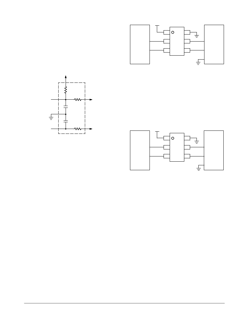
Full
Speed Devices
The Pull up resistor (Rpu) is connected to the D+ Line.
The terminal 1 is connected to the Voltage Supply Line
(V
BUS
) while the terminal 6 is connected to ground. The
input of the D+ line is connected in the terminal 3 which
outputs from the terminal 4. Finally, the input of the D
line
is connected in the terminal 2 which outputs from the
terminal 5. The Figure 8 shows the connections of the
STF202 device for “Full
Speed devices”.
Figure 8.
GND
D
D+
STF202
6
5
4
1
2
3
USB
Controller
D
D+
5 V
Peripheral
Low
Speed Devices
The Pull up resistor (Rpu) is connected to the D
Line. The
terminal 1 is connected to the Voltage Supply Line (V
BUS
)
while the terminal 6 is connected to ground. The input of the
D
line is connected in the terminal 3 which outputs from the
terminal 4. Finally, the input of the D+ line is connected in
the terminal 2 which outputs from the terminal 5. The Figure
9 shows the connections of the STF202 device for
“Low
Speed devices”.
Figure 9.
GND
D+
D
STF202
6
5
4
1
2
3
USB
Controller
D+
D
5 V
Peripheral
相關(guān)PDF資料 |
PDF描述 |
|---|---|
| STI728107D1-70VGR | 8M X 72 EDO DRAM MODULE, 70 ns, DMA168 |
| STI728107D1-70VGU | 8M X 72 EDO DRAM MODULE, 70 ns, DMA168 |
| STPCG1MBRD | INTERCONNECTION DEVICE |
| STPCG5MBRD | INTERCONNECTION DEVICE |
| STPCG5MBYL | INTERCONNECTION DEVICE |
相關(guān)代理商/技術(shù)參數(shù) |
參數(shù)描述 |
|---|---|
| STF202-22T1/D | 制造商:未知廠家 制造商全稱:未知廠家 功能描述:EMI Filter with ESD Protection |
| STF202-22T1G | 功能描述:電磁干擾濾波器 Upstream USB Port Filter w/6V TVS RoHS:否 制造商:STMicroelectronics 電容:12 pF 電路類型: 最大直流電流: 最大直流電阻: 電壓額定值:6 V 容差: 端接類型:SMD/SMT 工作溫度范圍:- 30 C to + 85 C 系列:EMIF03 |
| STF202-22T1G | 制造商:ON Semiconductor 功能描述:Active Analog Filter IC |
| STF202-22T1G-CUT TAPE | 制造商:ON 功能描述:STF202-22T1G Series USB Filter with ESD Protection - TSOP-6 |
| STF202-22TC | 制造商:SEMTECH 制造商全稱:Semtech Corporation 功能描述:USB Upstream Port Filter & TVS For EMI Filtering and ESD Protection |
發(fā)布緊急采購(gòu),3分鐘左右您將得到回復(fù)。