- 您現(xiàn)在的位置:買賣IC網(wǎng) > PDF目錄32621 > SR820-C (RECTRON LTD) 8 A, 20 V, SILICON, RECTIFIER DIODE, TO-220AC PDF資料下載
參數(shù)資料
| 型號: | SR820-C |
| 廠商: | RECTRON LTD |
| 元件分類: | 整流器 |
| 英文描述: | 8 A, 20 V, SILICON, RECTIFIER DIODE, TO-220AC |
| 封裝: | ROHS COMPLIANT, PLASTIC, TO-220A, 2 PIN |
| 文件頁數(shù): | 1/3頁 |
| 文件大小: | 190K |
| 代理商: | SR820-C |
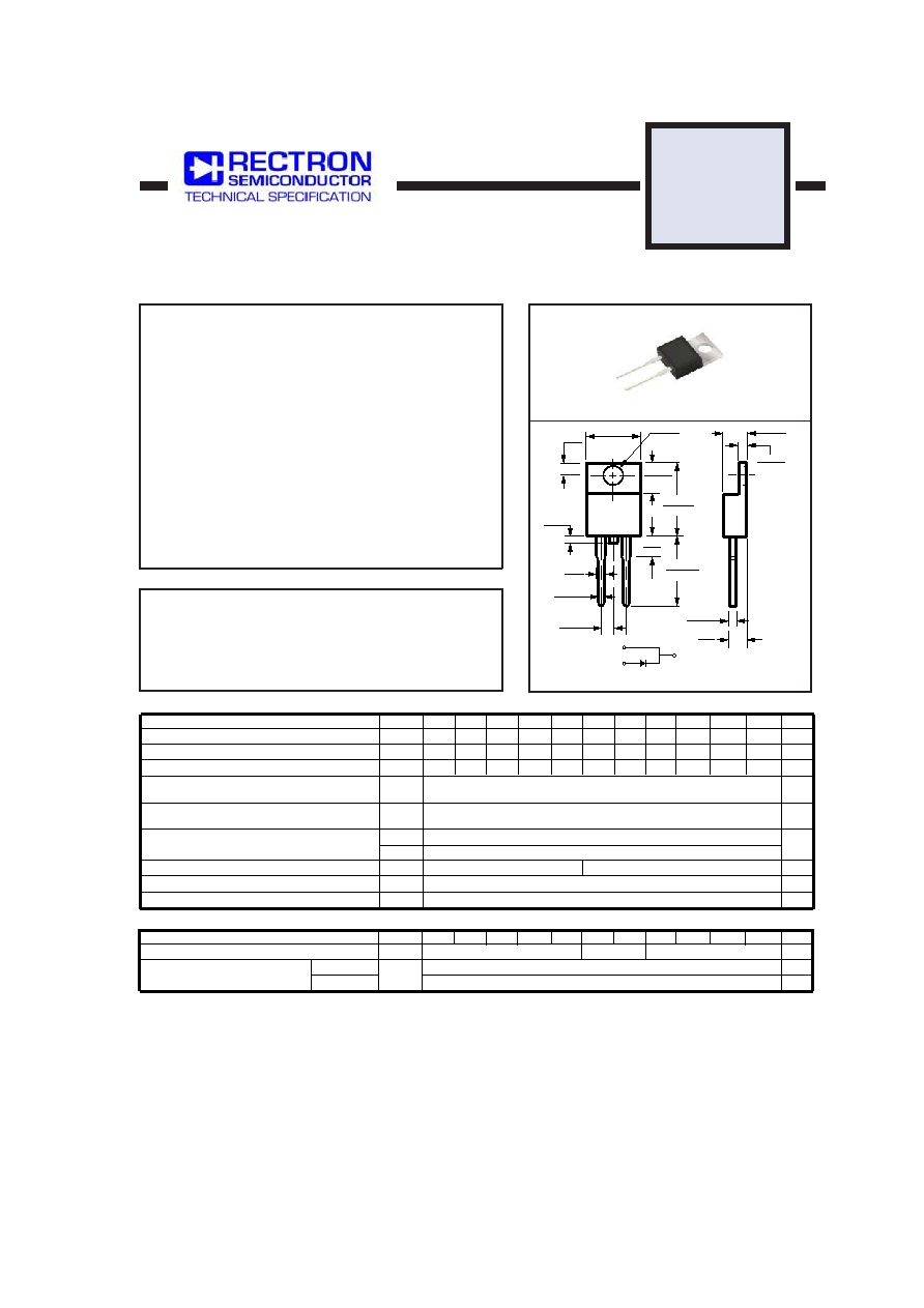
SCHOTTKY BARRIER RECTIFIER
VOLTAGE RANGE 20 to 200 Volts CURRENT 8.0 Amperes
FEATURES
MECHANICAL DATA
MAXIMUM RATINGS AND ELECTRICAL CHARACTERISTICS
Ratings at 25 oC ambient temperature unless otherwise specified.
Single phase, half wave, 60 Hz, resistive or inductive load.
For capacitive load, derate current by 20%.
SR8200
THRU
SR820
TO-220A
MAXIMUM RATINGS (@ TA=25 OC unless otherwise noted)
ELECTRICAL CHARACTERISTICS(@TA=25 OC unless otherwise noted)
Dimensions in inches and (millimeters)
.153 ( 3.9)
.413 ( 10.5)
.108
.051
.04 MAX.
.374 ( 9.5)
( 2.75)
( 1.3)
( 1.0)
.148 ( 3.8)
.053 ( 1.3)
.047 ( 1.2)
.270 ( 6.9)
.610 ( 15.5)
.583 (14.8)
.102 ( 2.6)
.091 ( 2.3)
.583 ( 14.8)
.157
.126
( 4.0)
( 3.2)
.531 (13.5)
.020 ( 0.5)
.012 ( 0.3)
.230 ( 5.8)
.187 ( 4.7)
.146 ( 3.7)
.035 (0.9 )
.028 ( 0.7)
PIN
1
2
PIN 1
PIN 2
HEATSINK
* Low switching noise
* Low forward voltage drop
* Low thermal resistance
* High current capability
* High surge capabitity
* High reliability
* Case: To-220A molded plastic
* Epoxy: Device has UL flammability classification 94V-O
* Lead: MIL-STD-202E method 208C guaranteed
* Mounting position: Any
* Weight: 2.24 grams
RATINGS
Maximum Recurrent Peak Reverse Voltage
Maximum RMS Voltage
Maximum DC Blocking Voltage
Maximum Average Forward Rectified Current
at Derating Case Temperature
Peak Forward Surge Current 8.3 ms single half sine-wave
superimposed on rated load (JEDEC method)
Typical Thermal Resistance (Note 1)
Typical Junction Capacitance (Note 3)
SYMBOL
VRRM
VDC
IFSM
CJ
TSTG
VRMS
UNITS
Volts
Amps
8.0
150
2.5
60
700
Amps
0
C/W
0
C
Storage Temperature Range
R q J C
R q J A
IO
pF
Operating Temperature Range
TJ
SR820
20
150
-55 to + 150
0
C
SR835
SR830
SR840 SR845 SR850 SR860
30
35
40
45
50
60
14
21
25
28
32
35
42
20
30
35
40
45
50
60
SR880 SR8100 SR8150 SR8200
SR820
SR835
SR830
SR840 SR845 SR850 SR860 SR880 SR8100 SR8150 SR8200
80
100
150
200
80
100
150
200
56
70
105
140
450
NOTES : 1. Thermal Resistance : Heat-sink mounted.
2. Suffix “R” for Reverse Polarity.
3. Measured at 1 MHz and applied reverse voltage of 4.0 volts.
4. "Fully ROHS compliant", "100% Sn plating (Pb-free)".
2006-11
CHARACTERISTICS
Maximum Average Reverse Current
at Rated DC Blocking Voltage
VF
SYMBOL
IR
mA
Maximum Instantaneous Forward Voltage at 8.0A DC
Volts
0.2
2
@TA = 25
oC
@TA = 100
oC
.65
mA
UNITS
.75
.85
相關(guān)PDF資料 |
PDF描述 |
|---|---|
| SR880R | 8 A, 80 V, SILICON, RECTIFIER DIODE, TO-220AC |
| SR8100 | 8 A, 100 V, SILICON, RECTIFIER DIODE, TO-220AC |
| SRA255GP-BP | 35 A, 600 V, SILICON, RECTIFIER DIODE |
| SRA256GP-BP | 35 A, 800 V, SILICON, RECTIFIER DIODE |
| SRA251GP-BP | 35 A, 50 V, SILICON, RECTIFIER DIODE |
相關(guān)代理商/技術(shù)參數(shù) |
參數(shù)描述 |
|---|---|
| SR820CT | 制造商:CHENDA 制造商全稱:Chendahang Electronics Co., Ltd 功能描述:SCHOTTKY BARRIER RECTIFIER |
| SR820E | 制造商:SECOS 制造商全稱:SeCoS Halbleitertechnologie GmbH 功能描述:8.0AMP Schottky Barrier Rectifiers |
| SR820E_08 | 制造商:SECOS 制造商全稱:SeCoS Halbleitertechnologie GmbH 功能描述:8.0AMP Schottky Barrier Rectifiers |
| SR820K | 制造商:RECTRON 制造商全稱:Rectron Semiconductor 功能描述:SCHOTTKY BARRIER RECTIFIER VOLTAGE RANGE 20 to 200 Volts CURRENT 8.0 Ampere |
| SR820R | 制造商:SEMTECH_ELEC 制造商全稱:SEMTECH ELECTRONICS LTD. 功能描述:SCHOTTKY BARRIER RECTIFIER |
發(fā)布緊急采購,3分鐘左右您將得到回復(fù)。