- 您現(xiàn)在的位置:買賣IC網(wǎng) > PDF目錄372223 > SPX2950CN-3.0 150mA Low Dropout Voltage Regulators PDF資料下載
參數(shù)資料
| 型號: | SPX2950CN-3.0 |
| 元件分類: | 基準電壓源/電流源 |
| 英文描述: | 150mA Low Dropout Voltage Regulators |
| 中文描述: | 150mA的低壓差穩(wěn)壓器 |
| 文件頁數(shù): | 3/13頁 |
| 文件大小: | 135K |
| 代理商: | SPX2950CN-3.0 |
3
Rev. 3/6/03
SPX2950/SPX2951 150mA Low Dropout Voltage Regulator
Copyright 2003 Sipex Corporation
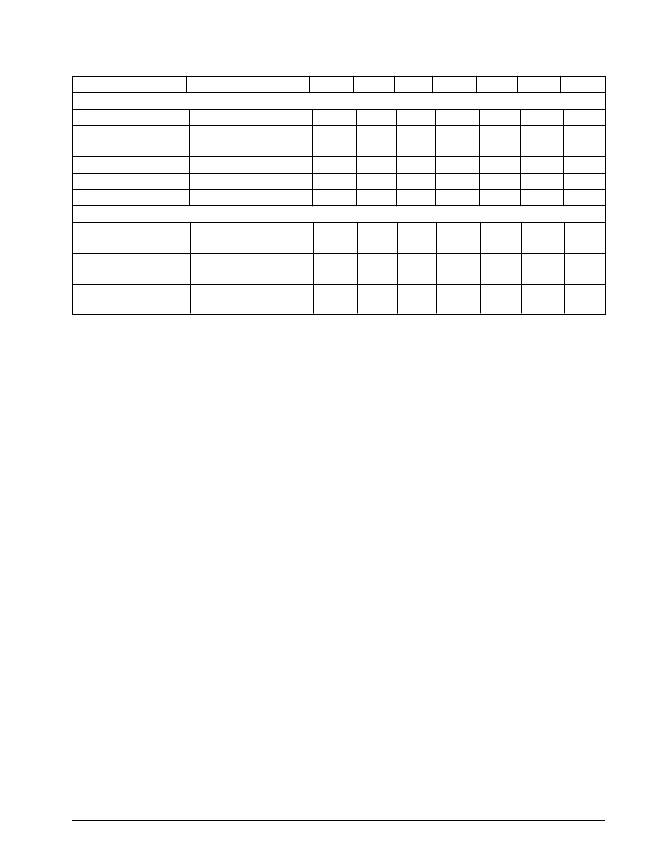
PARAMETER
Error Comparator
Output Leakage Current
Output Low Voltage
CONDITIONS
MIN
TYP
MAX
MIN
TYP
MAX
UNITS
V
0H
=30V
V
IN
=V
O
-0.5V
I
0L
=400
μ
A
(Note 7)
(Note 7)
(Note 7)
0.01
150
1
0.01
150
1
μ
A
mV
250
250
Upper Threshold Voltage
Lower Threshold Voltage
Hysteresis
Shutdown Input
Input Logic Voltage
40
60
75
15
40
60
75
15
mV
mV
mV
95
95
Low (Regulator ON)
High (Regulator OFF)
1.3
0.7
1.3
0.7
V
V
μ
A
μ
A
μ
A
2.0
2.0
Shutdown Pin Input Current V
S
=2.4V
30
400
3
50
800
10
30
400
3
50
800
10
V
S
=30V
(Note 8)
Regulator Output Current
in Shutdown
ELECTRICAL CHARACTERISTICS: Continued
Electrical characteristics at V
=
V
O
+1V, I
L
=100
μ
A, C
L
=1
μ
F (note 2) T
A
=25
°
C,
unless otherwise specified.
Boldface
applies over
the full operating temperature range.
Note 1:
Output or reference voltage temperature coefficients defined as the worst case voltage change divided by
the total temperature range.
Note 2:
Unless otherwise specified all limits are guaranteed for T
= 25
°
C, V
= V
+1V, I
= 100
μ
A and C
L
= 1
μ
F.
Additional conditions for the 8-pin versions are feedback tied to 5V tap and output tied to output sense (V
OUT
= 5V)
and V
SHUTDOWN
≤
0.8V.
Note 3:
Regulation is measured at constant junction temperature, using pulse testing with a low duty cycle. Changes
in output voltage
due to heating effects are covered under the specification for thermal regulation.
Note 4:
Line regulation for the SPX2951 is tested at I
L
= 1mA. See typical performance characteristics for line
regulation versus temperature and load current.
Note 5:
Dropout voltage is defined as the input to output differential at which the output voltage drops 100mV below
its nominal value measured at 1V differential. At very low values of programmed output voltage, the minimum input
supply voltage of 2V ( 2.3V over temperature) must be taken into account.
Note 6:
V
≤
V
≤
(V
-1V),2.3
≤
V
≤
30V, 100
μ
A
≤
I
≤
150mA, T
≤
T
.
Note 7:
Comparator thresholds are expressed in terms of a voltage differential at the feedback terminal below the
nominal reference voltage measured at 6V input. To express these thresholds in terms of output voltage change,
multiply by the error amplifier gain = V
/V
= (R
+ R
)/R
For example, at a programmed output voltage of 5V,
the error output is guaranteed to go low when the output drops by 95mV x 5V/1.235 = 384mV. Thresholds remain
constant as a percent of V
OUT
as V
OUT
is varied, with the dropout warning occurring at typically 5% below nominal,
7.5% guaranteed.
Note 8:
V
SHUTDOWN
≥
2V, V
IN
≤
30V, V
OUT
= 0, Feedback pin tied to 5V/ 3.3V tap.
相關(guān)PDF資料 |
PDF描述 |
|---|---|
| SPX2951CS-3.0 | 150mA Low Dropout Voltage Regulators |
| SPX2951CS-3.3 | 150mA Low Dropout Voltage Regulators |
| SPX2954AN-3.3 | VARISTOR 14VRMS 0805 SMD AUTO |
| SPX2954AN-5.0 | VARISTOR 30VRMS 1210 SMD |
| SPX2954T5-3.3 | 250 mA Low Drop Out Voltage Regulator |
相關(guān)代理商/技術(shù)參數(shù) |
參數(shù)描述 |
|---|---|
| SPX2950CN-5.0 | 制造商:SIPEX 制造商全稱:Sipex Corporation 功能描述:150mA Low Dropout Voltage Regulators |
| SPX2950CN-L-3-3 | 制造商:Rochester Electronics LLC 功能描述: 制造商:Exar Corporation 功能描述: |
| SPX2950CN-L-5-0 | 制造商:Rochester Electronics LLC 功能描述: 制造商:Exar Corporation 功能描述: |
| SPX2951 | 制造商:SIPEX 制造商全稱:Sipex Corporation 功能描述:150mA Low Dropout Voltage Regulator |
| SPX2951ACS-3.0 | 制造商:SIPEX 制造商全稱:Sipex Corporation 功能描述:150mA Low Dropout Voltage Regulators |
發(fā)布緊急采購,3分鐘左右您將得到回復。