- 您現(xiàn)在的位置:買(mǎi)賣(mài)IC網(wǎng) > PDF目錄372174 > SP3220U Low Power 5V RS232 Dual Driver/Receiver with 0.1?μF Capacitors; Package: SO; No of Pins: 16; Temperature Range: -40?°C to 85?°C PDF資料下載
參數(shù)資料
| 型號(hào): | SP3220U |
| 元件分類(lèi): | 外設(shè)及接口 |
| 英文描述: | Low Power 5V RS232 Dual Driver/Receiver with 0.1?μF Capacitors; Package: SO; No of Pins: 16; Temperature Range: -40?°C to 85?°C |
| 中文描述: | 電可擦除可編程邏輯器件 |
| 文件頁(yè)數(shù): | 11/18頁(yè) |
| 文件大小: | 115K |
| 代理商: | SP3220U |
第1頁(yè)第2頁(yè)第3頁(yè)第4頁(yè)第5頁(yè)第6頁(yè)第7頁(yè)第8頁(yè)第9頁(yè)第10頁(yè)當(dāng)前第11頁(yè)第12頁(yè)第13頁(yè)第14頁(yè)第15頁(yè)第16頁(yè)第17頁(yè)第18頁(yè)
11
Rev. 7/8/03 SP3220B/U +3.0 to +5.0V RS-232 Transceivers
Copyright 2003 Sipex Corporation
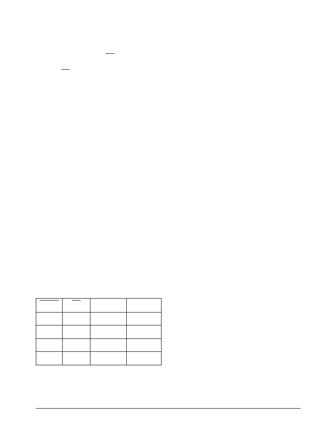
Table 2. Truth Table Logic for Shutdown and
Enable Control
N
D
H
S
N
E
T
U
O
x
T
T
U
O
x
R
0
0
e
T
e
v
A
0
1
e
T
e
T
1
0
e
v
A
e
v
A
1
1
e
v
A
e
T
Receivers
The receiver converts EIA/TIA-232 levels to
TTL or CMOS logic output levels. The receiver
has an inverting high-impedance output. This
receiver output (RxOUT) is at high-impedance
when the enable control EN = HIGH. In the
shutdown mode, the receiver can be active or
inactive. EN has no effect on TxOUT. The truth
table logic of the
SP3220B/U
driver and receiver
outputs can be found in
Table 2
.
Since receiver input is usually from a transmission
line where long cable lengths and system
interference can degrade the signal, the inputs
have a typical hysteresis margin of 300mV.
This ensures that the receiver is virtually
immune to noisy transmission lines. Should an
input be left unconnected, a 5k
pulldown
resistor to ground will commit the output of the
receiver to a HIGH state.
Charge Pump
The charge pump is a
Sipex
–patented design
(U.S. 5,306,954) and uses a unique approach
compared to older less–efficient designs. The
charge pump still requires four external
capacitors, but uses a four–phase voltage shifting
technique to attain symmetrical 5.5V power
supplies. The internal power supply consists of
a regulated dual charge pump that provides
output voltages 5.5V regardless of the input
voltage (V
CC
) over the +3.0V to +5.5V range.
In most circumstances, decoupling the power
supply can be achieved adequately using a 0.1
μ
F
bypass capacitor at C5 (refer to
Figures 11
).
In applications that are sensitive to power-
supply noise, decouple V
to ground with a
capacitor of the same value as charge-pump
capacitor C1. Physically connect bypass
capacitors as close to the IC as possible.
The charge pumps operate in a discontinuous
mode using an internal oscillator. If the output
voltages are less than a magnitude of 5.5V, the
charge pumps are enabled. If the output voltage
exceed a magnitude of 5.5V, the charge pumps
are disabled. This oscillator controls the four
phases of the voltage shifting. A description of
each phase follows.
Phase 1
— V
charge storage — During this phase of
the clock cycle, the positive side of capacitors
C
and C
are initially charged to V
. C
switched to GND and the charge in C
transferred to C
the voltage potential across capacitor C
2
is now
2 times V
CC
.
+
is then
–
is
–
. Since C
+
is connected to V
,
Phase 2
— V
transfer — Phase two of the clock
connects the negative terminal of C
to the V
SS
storage capacitor and the positive terminal of C
2
to GND. This transfers a negative generated
voltage to C
. This generated voltage is
regulated to a minimum voltage of -5.5V.
Simultaneous with the transfer of the voltage to
C
, the positive side of capacitor C
is switched
to V
CC
and the negative side is connected to GND.
Phase 3
— V
charge storage — The third phase of the
clock is identical to the first phase — the charge
transferred in C
produces –V
in the negative
terminal of C
, which is applied to the negative
side of capacitor C
. Since C
voltage potential across C
2
is 2 times V
CC
.
+
is at V
CC
, the
相關(guān)PDF資料 |
PDF描述 |
|---|---|
| SP3220UCY | Low Power 5V RS232 Dual Driver/Receiver with 0.1?μF Capacitors; Package: SO; No of Pins: 16; Temperature Range: -40?°C to 85?°C |
| SP3220BEA | Low Power 5V RS232 Dual Driver/Receiver with 0.1?μF Capacitors; Package: SO; No of Pins: 16; Temperature Range: -40?°C to 85?°C |
| SP3220BET | Low Power 5V RS232 Dual Driver/Receiver with 0.1?μF Capacitors; Package: SO; No of Pins: 16; Temperature Range: -40?°C to 85?°C |
| SP3220BEY | Low Power 5V RS232 Dual Driver/Receiver with 0.1?μF Capacitors; Package: SO; No of Pins: 16; Temperature Range: -40?°C to 85?°C |
| SP3220UCT | 320 x 240 pixel format, LED or CFL Backlight |
相關(guān)代理商/技術(shù)參數(shù) |
參數(shù)描述 |
|---|---|
| SP3220UCA | 制造商:SIPEX 制造商全稱(chēng):Sipex Corporation 功能描述:High Speed +3.0V to +5.5V RS-232 Driver/Receiver Pair |
| SP3220UCT | 制造商:SIPEX 制造商全稱(chēng):Sipex Corporation 功能描述:High Speed +3.0V to +5.5V RS-232 Driver/Receiver Pair |
| SP3220UCY | 制造商:SIPEX 制造商全稱(chēng):Sipex Corporation 功能描述:High Speed +3.0V to +5.5V RS-232 Driver/Receiver Pair |
| SP3220UEA | 制造商:SIPEX 制造商全稱(chēng):Sipex Corporation 功能描述:High Speed +3.0V to +5.5V RS-232 Driver/Receiver Pair |
| SP3220UET | 制造商:SIPEX 制造商全稱(chēng):Sipex Corporation 功能描述:High Speed +3.0V to +5.5V RS-232 Driver/Receiver Pair |
發(fā)布緊急采購(gòu),3分鐘左右您將得到回復(fù)。