- 您現(xiàn)在的位置:買賣IC網(wǎng) > PDF目錄9980 > SI4126-F-GM (Silicon Laboratories Inc)IC WLAN SYNTH (RF2/IF) 28MLP PDF資料下載
參數(shù)資料
| 型號(hào): | SI4126-F-GM |
| 廠商: | Silicon Laboratories Inc |
| 文件頁數(shù): | 9/34頁 |
| 文件大小: | 0K |
| 描述: | IC WLAN SYNTH (RF2/IF) 28MLP |
| 標(biāo)準(zhǔn)包裝: | 60 |
| 類型: | * |
| 驅(qū)動(dòng)器/接收器數(shù): | * |
| 規(guī)程: | * |
| 電源電壓: | 2.7 V ~ 3.6 V |
| 安裝類型: | 表面貼裝 |
| 封裝/外殼: | 28-VFQFN 裸露焊盤 |
| 供應(yīng)商設(shè)備封裝: | 28-QFN(5x5) |
| 包裝: | 管件 |
| 其它名稱: | 336-1289-5 |
第1頁第2頁第3頁第4頁第5頁第6頁第7頁第8頁當(dāng)前第9頁第10頁第11頁第12頁第13頁第14頁第15頁第16頁第17頁第18頁第19頁第20頁第21頁第22頁第23頁第24頁第25頁第26頁第27頁第28頁第29頁第30頁第31頁第32頁第33頁第34頁
Si4136/Si4126
Rev. 1.41
17
Table 6 summarizes the characteristics of the IF VCO.
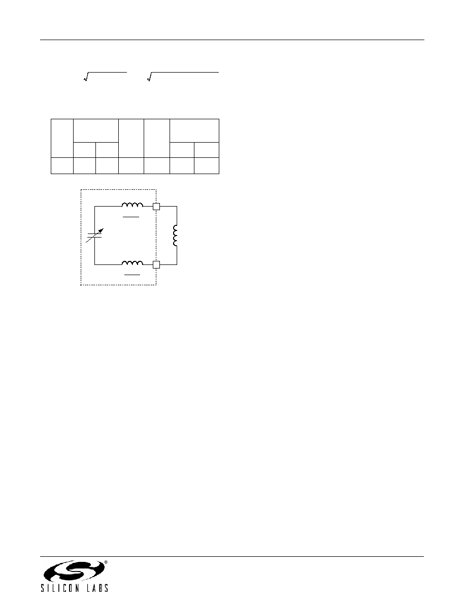
Figure 14. Example of IF External Inductor
As
a
design
example,
suppose
synthesizing
frequencies in a 30 MHz band between 735 MHz and
765 MHz is desired. The center frequency should be
defined as midway between the two extremes, or
750 MHz. The PLL will be able to adjust the VCO output
frequency ±5% of the center frequency, or ±37.5 MHz of
750 MHz
(i.e.,
from
approximately
713 MHz
to
788 MHz). The IF VCO has a CNOM of 6.5 pF, and a
6.9 nH inductance (correct to two digits) in parallel with
this capacitance will yield the desired center frequency.
An external inductance of 4.8 nH should be connected
between IFLA and IFLB, as shown in Figure 14. This, in
addition to 2.1 nH of package inductance, will present
the
correct
total
inductance
to
the
VCO.
In
manufacturing, the external inductance can vary ±10%
of its nominal value and the Si4136 will correct for the
variation with the self-tuning algorithm.
For more information on designing the external trace
inductor, please refer to Application Note 31.
2.3. Self-Tuning Algorithm
The
self-tuning
algorithm
is
initiated
immediately
following power-up of a PLL or, if the PLL is already
powered, following a change in its programmed output
frequency. This algorithm attempts to tune the VCO so
that its free-running frequency is near the desired output
frequency. In so doing, the algorithm will compensate
for manufacturing tolerance errors in the value of the
external inductance connected to the IF VCO. It will also
reduce the frequency error for which the PLL must
correct to get the precise desired output frequency. The
self-tuning algorithm will leave the VCO oscillating at a
frequency in error by somewhat less than 1% of the
desired output frequency.
After self-tuning, the PLL controls the VCO oscillation
frequency. The PLL will complete frequency locking,
eliminating any remaining frequency error. Thereafter, it
will maintain frequency-lock, compensating for effects
caused by temperature and supply voltage variations.
The Si4136’s self-tuning algorithm will compensate for
component value errors at any temperature within the
specified temperature range. However, the ability of the
PLL to compensate for drift in component values that
occur
after
self-tuning
is
limited.
For
external
inductances with temperature coefficients around ±150
ppm/°C, the PLL will be able to maintain lock for
changes in temperature of approximately ±30°C.
Applications where the PLL is regularly powered-down
or the frequency is periodically reprogrammed minimize
or eliminate the potential effects of temperature drift
because the VCO is re-tuned in either case. In
applications where the ambient temperature can drift
substantially after self-tuning, it may be necessary to
monitor the lock-detect bar (LDETB) signal on the
AUXOUT pin to determine whether a PLL is about to
run out of locking capability. (See “2.9. Auxiliary Output
(AUXOUT)” for how to select LDETB.) The LDETB
signal will be low after self-tuning has completed but will
rise when either the IF or RF PLL nears the limit of its
compensation range. (LDETB will also be high when
either PLL is executing the self-tuning algorithm.) The
output frequency will still be locked when LDETB goes
high, but the PLL will eventually lose lock if the
temperature continues to drift in the same direction.
Therefore, if LDETB goes high both the IF and RF PLLs
should promptly be re-tuned by initiating the self-tuning
algorithm.
2.4. Output Frequencies
The IF and RF output frequencies are set by
programming the R- and N-Divider registers. Each PLL
has its own R and N registers so that each can be
Table 6. Si4136-BT/GT VCO Characteristics
VCO
Fcen Range
(MHz)
Cnom
(pF)
Lpkg
(nH)
Lext Range
(nH)
Min
Max
Min
Max
IF
526
952
6.5
2.1
2.2
12.0
f
CEN
1
2
L
TOT
C
NOM
---------------------------------------------
1
2
L
PKG
L
EXT
+
C
NOM
----------------------------------------------------------------------
==
Si4136
L
PKG
2
L
PKG
2
L
EXT
IFLB
IFLA
相關(guān)PDF資料 |
PDF描述 |
|---|---|
| KAD5512HP-12Q48 | IC ADC 12BIT 125MSPS SGL 48-QFN |
| VE-B12-MW-F2 | CONVERTER MOD DC/DC 15V 100W |
| VE-B12-MW-F1 | CONVERTER MOD DC/DC 15V 100W |
| KAD2710C-21Q68 | IC ADC 10BIT 210MSPS SGL 68-QFN |
| VI-B12-MW-F4 | CONVERTER MOD DC/DC 15V 100W |
相關(guān)代理商/技術(shù)參數(shù) |
參數(shù)描述 |
|---|---|
| SI4126-F-GMR | 功能描述:射頻無線雜項(xiàng) WLAN Synthesizer RF2/IF RoHS:否 制造商:Texas Instruments 工作頻率:112 kHz to 205 kHz 電源電壓-最大:3.6 V 電源電壓-最小:3 V 電源電流:8 mA 最大功率耗散: 工作溫度范圍:- 40 C to + 110 C 封裝 / 箱體:VQFN-48 封裝:Reel |
| SI4126M-EVB | 功能描述:射頻開發(fā)工具 802.11b and ISM Band RoHS:否 制造商:Taiyo Yuden 產(chǎn)品:Wireless Modules 類型:Wireless Audio 工具用于評(píng)估:WYSAAVDX7 頻率: 工作電源電壓:3.4 V to 5.5 V |
| SI4128DY | 制造商:VISHAY 制造商全稱:Vishay Siliconix 功能描述:N-Channel 30-V (D-S) MOSFET |
| Si4128DY-T1-E3 | 功能描述:MOSFET 30V 10.9A 5.0W 24mohm @ 10V RoHS:否 制造商:STMicroelectronics 晶體管極性:N-Channel 汲極/源極擊穿電壓:650 V 閘/源擊穿電壓:25 V 漏極連續(xù)電流:130 A 電阻汲極/源極 RDS(導(dǎo)通):0.014 Ohms 配置:Single 最大工作溫度: 安裝風(fēng)格:Through Hole 封裝 / 箱體:Max247 封裝:Tube |
| SI4128DY-T1-GE3 | 功能描述:MOSFET 30V 10.9A 5.0W RoHS:否 制造商:STMicroelectronics 晶體管極性:N-Channel 汲極/源極擊穿電壓:650 V 閘/源擊穿電壓:25 V 漏極連續(xù)電流:130 A 電阻汲極/源極 RDS(導(dǎo)通):0.014 Ohms 配置:Single 最大工作溫度: 安裝風(fēng)格:Through Hole 封裝 / 箱體:Max247 封裝:Tube |
發(fā)布緊急采購,3分鐘左右您將得到回復(fù)。