- 您現(xiàn)在的位置:買賣IC網(wǎng) > PDF目錄31064 > SBLB20L15 (VISHAY SEMICONDUCTORS) 20 A, 15 V, SILICON, RECTIFIER DIODE, TO-263AB PDF資料下載
參數(shù)資料
| 型號: | SBLB20L15 |
| 廠商: | VISHAY SEMICONDUCTORS |
| 元件分類: | 整流器 |
| 英文描述: | 20 A, 15 V, SILICON, RECTIFIER DIODE, TO-263AB |
| 封裝: | PLASTIC PACKAGE-3 |
| 文件頁數(shù): | 1/4頁 |
| 文件大?。?/td> | 69K |
| 代理商: | SBLB20L15 |
SBL20L15, SBLF20L15, SBLB20L15
Vishay Semiconductors
formerly General Semiconductor
Document Number 88729
www.vishay.com
02-Jul-02
1
New Product
Low VF Schottky OR-ing Rectifier
Reverse Voltage 15V
Forward Current 20A
0.08
(2.032)
0.24
(6.096)
0.42
(10.66)
0.63
(17.02)
0.12
(3.05)
0.33
(8.38)
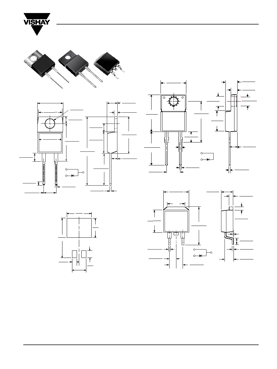
Mounting Pad Layout TO-263AB
Dimensions in inches
and (millimeters)
0.380 (9.65)
0.411 (10.45)
0.320 (8.13)
0.360 (9.14)
0.591 (15.00)
0.624 (15.85)
1
2
0.245 (6.22)
MIN
K
0.027 (0.686)
0.037 (0.940)
0.105 (2.67)
0.095 (2.41)
0.205 (5.20)
0.195 (4.95)
K
0.160 (4.06)
0.190 (4.83)
0.045 (1.14)
0.055 (1.40)
0.021 (0.53)
0.014 (0.36)
0.110 (2.79)
0.140 (3.56)
0.090 (2.29)
0.110 (2.79)
0.047 (1.19)
0.055 (1.40)
PIN 1
PIN 2
K - HEATSINK
0-0.01 (0-0.254)
0.060 (1.52)
0.405 (10.27)
0.383 (9.72)
0.191 (4.85)
0.171 (4.35)
0.600 (15.5)
0.580 (14.5)
0.560 (14.22)
0.530 (13.46)
0.037 (0.94)
0.027 (0.69)
0.140 (3.56)
0.130 (3.30)
0.350 (8.89)
0.330 (8.38)
0.188 (4.77)
0.172 (4.36)
0.110 (2.80)
0.100 (2.54)
0.131 (3.39)
0.122 (3.08)
0.110 (2.80)
0.100 (2.54)
0.022 (0.55)
0.014 (0.36)
0.205 (5.20)
0.195 (4.95)
12
PIN
DIA.
PIN 1
PIN 2
0.676 (17.2)
0.646 (16.4)
ITO-220AC (SBLF20L25)
TO-220AC (SBL20L15)
TO-263AB (SBLB20L25)
0.154 (3.91)
0.148 (3.74)
DIA.
0.113 (2.87)
0.103 (2.62)
0.185 (4.70)
0.175 (4.44)
0.055 (1.39)
0.045 (1.14)
0.145 (3.68)
0.135 (3.43)
0.350 (8.89)
0.330 (8.38)
0.160 (4.06)
0.140 (3.56)
0.037 (0.94)
0.027 (0.68)
0.205 (5.20)
0.195 (4.95)
0.560 (14.22)
0.530 (13.46)
0.022 (0.56)
0.014 (0.36)
0.110 (2.79)
0.100 (2.54)
12
1.148 (29.16)
1.118 (28.40)
0.105 (2.67)
0.095 (2.41)
0.410 (10.41)
0.390 (9.91)
0.635 (16.13)
0.625 (15.87)
0.603 (15.32)
0.573 (14.55)
PIN
0.415 (10.54) MAX.
PIN 1
PIN 2
CASE
0.370 (9.40)
0.360 (9.14)
Mechanical Data
Case: JEDEC TO-220AC, ITO-220AC & TO-263AB mold-
ed plastic body
Terminals: Plated leads, solderable per
MIL-STD-750, Method 2026
High temperature soldering guaranteed:
250°C/10 seconds, 0.25" (6.35mm) from case
Polarity: As marked
Mounting Position: Any
Mounting Torque: 10 in-lbs maximum
Weight: 0.08 oz., 2.24 g
Features
Plastic package has Underwriters Laboratory
Flammability Classifications 94V-0
Metal silicon junction, majority carrier conduction
Low power loss, high efficiency
Guardring for overvoltage protection
For use in low voltage, high frequency inverters, free
wheeling, and polarity protection applications
Optimized for OR-ing applications
相關(guān)PDF資料 |
PDF描述 |
|---|---|
| SBLB20L15-31 | 20 A, 15 V, SILICON, RECTIFIER DIODE, TO-263AB |
| SBLF20L15-45 | 20 A, 15 V, SILICON, RECTIFIER DIODE, TO-220AC |
| SBLB25LB20CT | 12.5 A, 20 V, SILICON, RECTIFIER DIODE, TO-263AB |
| SBLF25LF30CT | 12.5 A, 30 V, SILICON, RECTIFIER DIODE |
| SBLF25LF25CT | 12.5 A, 25 V, SILICON, RECTIFIER DIODE |
相關(guān)代理商/技術(shù)參數(shù) |
參數(shù)描述 |
|---|---|
| SBLB20L15/31 | 制造商:Vishay Intertechnologies 功能描述:Diode Schottky 15V 20A 3-Pin(2+Tab) TO-263AB T/R |
| SBLB25100CT | 制造商:BILIN 制造商全稱:Galaxy Semi-Conductor Holdings Limited 功能描述:SCHOTTKY BARRIER RECTIFIER |
| SBLB2530CT | 制造商:BILIN 制造商全稱:Galaxy Semi-Conductor Holdings Limited 功能描述:SCHOTTKY BARRIER RECTIFIER |
| SBLB2535CT | 制造商:BILIN 制造商全稱:Galaxy Semi-Conductor Holdings Limited 功能描述:SCHOTTKY BARRIER RECTIFIER |
| SBLB2545CT | 制造商:BILIN 制造商全稱:Galaxy Semi-Conductor Holdings Limited 功能描述:SCHOTTKY BARRIER RECTIFIER |
發(fā)布緊急采購,3分鐘左右您將得到回復(fù)。