- 您現(xiàn)在的位置:買賣IC網(wǎng) > PDF目錄32540 > SBF1640CT (LITE-ON SEMICONDUCTOR CORP) 16 A, 40 V, SILICON, RECTIFIER DIODE, TO-220AB PDF資料下載
參數(shù)資料
| 型號: | SBF1640CT |
| 廠商: | LITE-ON SEMICONDUCTOR CORP |
| 元件分類: | 整流器 |
| 英文描述: | 16 A, 40 V, SILICON, RECTIFIER DIODE, TO-220AB |
| 封裝: | PLASTIC, ITO-220AB, 3 PIN |
| 文件頁數(shù): | 1/2頁 |
| 文件大小: | 76K |
| 代理商: | SBF1640CT |
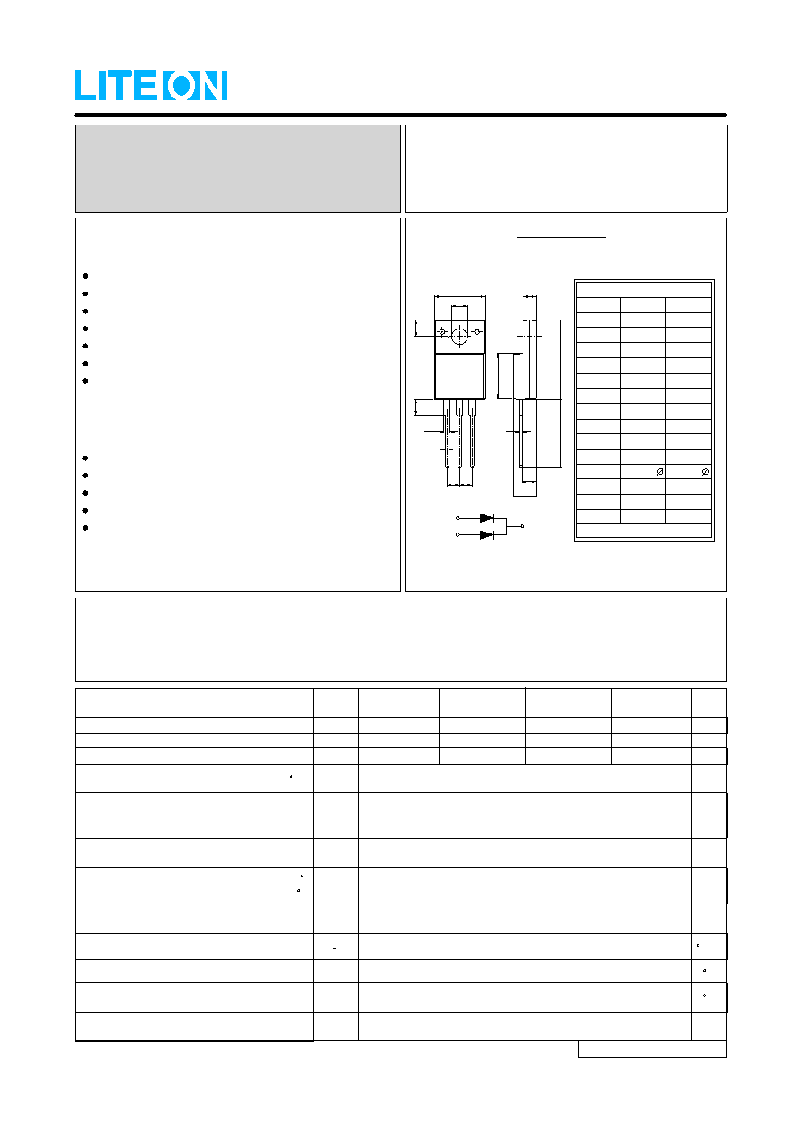
SBF1630CT thru 1645CT
MAXIMUM RATINGS AND ELECTRICAL CHARACTERISTICS
Ratings at 25
ambient temperature unless otherwise specified.
℃
Single phase, half wave, 60HZ, resistive or inductive load.
For capacitive load, derate current by 20%
FEATURES
Metal of silicon rectifier,majority carrier conducton
Guard ring for transient protection
Low power loss, high efficiency
High current capability, low VF
High surge capacity
Plastic package has UL flammability classification 94V-0
For use in low voltage,high frequency inverters,free
whelling,and polarity protection applications
MECHANICAL DATA
Case : ITO-220AB molded plastic
Polarity : As marked on the body
Weight : 0.06 ounces, 1.70 grams
Mounting position : Any
Max. mounting torque = 0.5 N.m (5.1 Kgf.cm)
NOTES : 1. 300us Pulse Width, 2% Duty Cycle.
2. Measured at 1.0MHz and applied reverse voltage of 4.0V DC.
3.Thermal Resistance Junction to Case.
VRMS
VDC
VRRM
I(AV)
IFSM
VF
Maximum Average Forward
Rectified Current (See Fig.1)
@TC
=95 C
Peak Forward Surge Current
8.3ms single half sine-wave
superimposed on rated load
Maximum Recurrent Peak Reverse Voltage
Maximum RMS Voltage
Maximum DC Blocking Voltage
Maximum Forward Voltage
at 8A DC (Note 1)
16
175
0.55
TJ
Operating Temperature Range
-55 to +125
C
TSTG
Storage Temperature Range
-55 to +150
C
Typical Thermal Resistance (Note 3)
R0JC
3.5
C/W
CJ
Typical Junction
Capacitance (Note 2)
500
pF
IR
@TJ =100 C
Maximum DC Reverse Current
at Rated DC Blocking Voltage
@TJ =25 C
0.5
50
mA
V
A
V
UNIT
V
CHARACTERISTICS
SYMBOL
SBF
1645CT
45
31.5
45
SBF
1640CT
40
28
40
SBF
1635CT
35
24.5
35
SBF
1630CT
30
21
30
SCHOTTKY BARRIER RECTIFIERS
REVERSE VOLTAGE - 30 to 45 Volts
FORWARD CURRENT - 16 Amperes
SEMICONDUCTOR
LITE-ON
REV. 2, May-2008, KTHC25
ITO-220AB
All Dimensions in millimeter
ITO-220AB
DIM.
MIN.
MAX.
A
C
D
E
F
G
H
B
15.50
16.50
10.40
10.0
3.00
3.50
9.30
9.00
2.90
3.60
13.46
14.22
1.15
1.70
0.75
2.70
N
M
L
K
J
I
1.00
2.40
0.70
0.45
3.00
3.30
4.36
4.77
2.48
2.80
2.50
G
I
C
E
J
B
K
A
M
D
L
N
F
H
PIN
1
2
3
Vdis
V
Dielectric Strengh from terminals to case,
AC with t=1 minute, RH<30%
2000
PIN 1
PIN 3
PIN 2
相關(guān)PDF資料 |
PDF描述 |
|---|---|
| SBG2030CT-13 | 20 A, 30 V, SILICON, RECTIFIER DIODE |
| SBG2040CT-13 | 20 A, 40 V, SILICON, RECTIFIER DIODE |
| SBG2045CT-13 | 20 A, 45 V, SILICON, RECTIFIER DIODE |
| SBL3030PT | 15 A, 30 V, SILICON, RECTIFIER DIODE, TO-247AD |
| SBT250-06L | 25 A, 60 V, SILICON, RECTIFIER DIODE |
相關(guān)代理商/技術(shù)參數(shù) |
參數(shù)描述 |
|---|---|
| SBF-18-8PS | 制造商:Amphenol Corporation 功能描述:RECEPT |
| SBF1MHS | 制造商:Banner Engineering 功能描述:MULTI-BEAM: 3/4 Wire Very High Speed Glass Fiber , Range: depends on fiber, Inpu |
| SBF2060CT-TU | 制造商:LITEON-SEMI 功能描述:20A, 60V SCHOTTKY |
| SBF-22-23PS | 制造商:Amphenol Corporation 功能描述:RECEPT |
發(fā)布緊急采購,3分鐘左右您將得到回復(fù)。